Bent transmission line suitable for various transmission lines

A transmission line and bending technology, applied in the directions of waveguides, circuits, electrical components, etc., can solve the problems of narrow bandwidth, complex matching circuit structure, large volume, etc., and achieve the effect of improving the calculation efficiency of modeling optimization and obvious advantages.

Inactive Publication Date: 2018-08-14
成都锐烽特科技有限公司
View PDF3 Cites 0 Cited by
  • Summary
  • Abstract
  • Description
  • Claims
  • Application Information

AI Technical Summary

Problems solved by technology

[0003] The existing matching circuit has complex structure, large volume, and narrow bandwidth, especially in rectangular waveguides, single-ridge rectangular waveguides, double-ridge rectangular waveguides and four-ridge rectangular waveguides, circular waveguides or elliptical waveguides, single-ridge circular waveguides or elliptical waveguides, In the bending connection of double ridge circular waveguide or elliptical waveguide, and four ridge circular waveguide or elliptical waveguide

Method used


Image

  • Bent transmission line suitable for various transmission lines
  • Bent transmission line suitable for various transmission lines
  • Bent transmission line suitable for various transmission lines

Examples


Embodiment 1

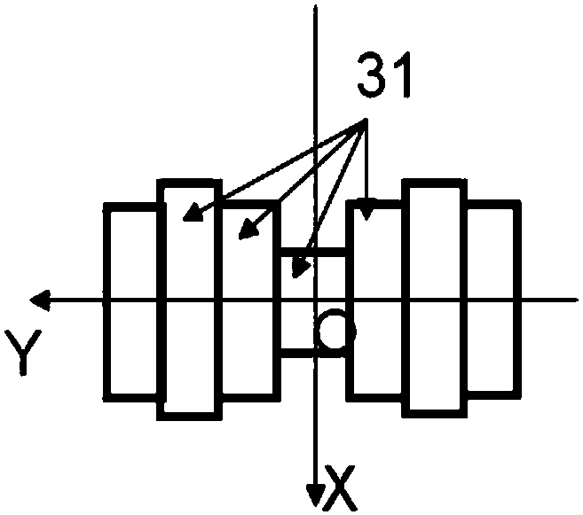
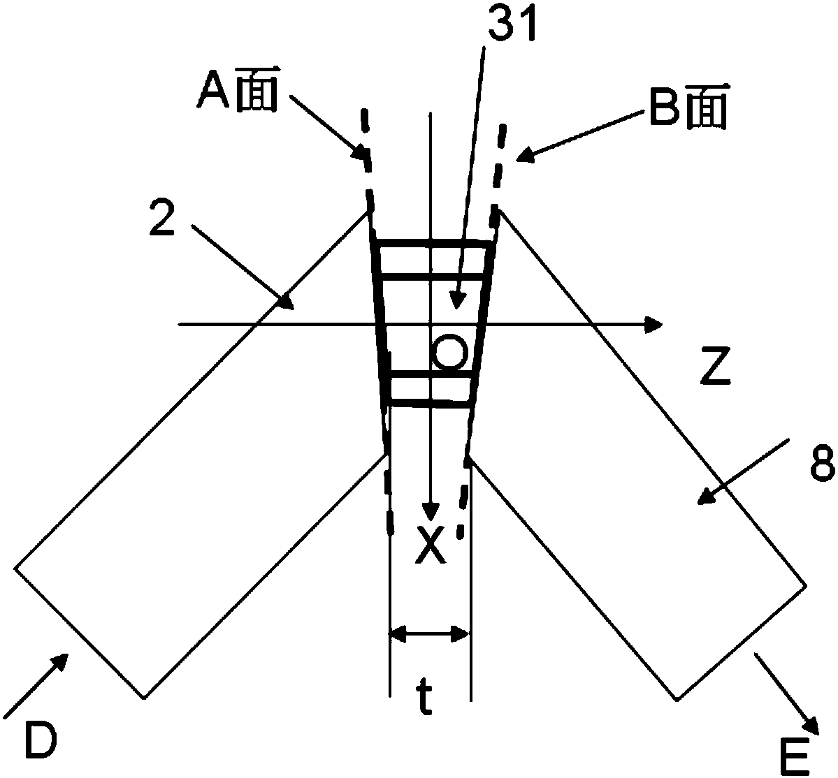
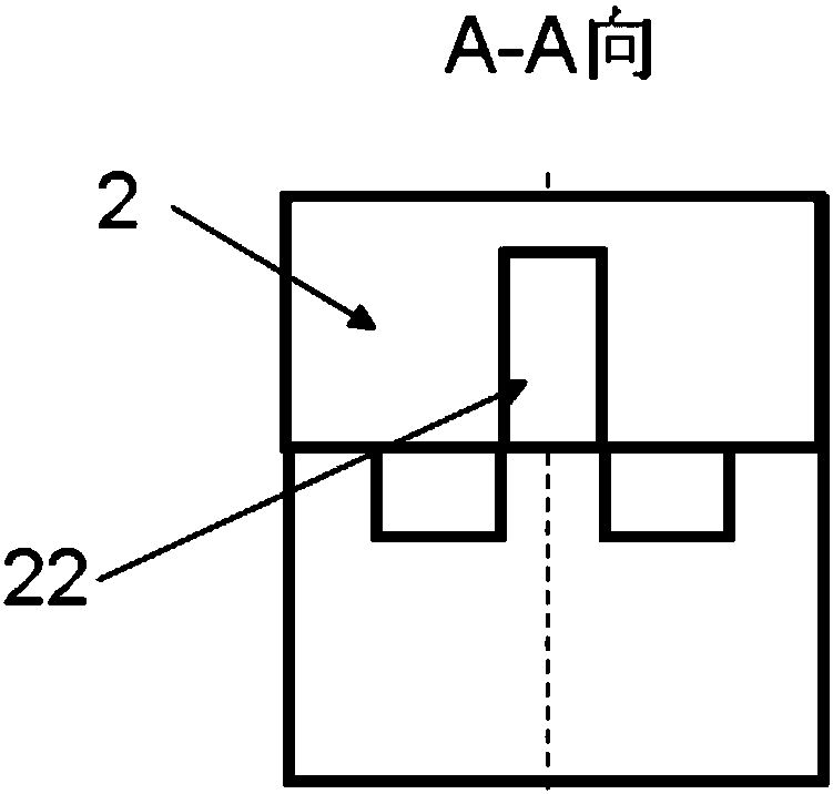
[0060] Such as Figure 1a with Figure 1b Shown.

[0061] The bend transmission line suitable for various transmission lines, including an input transmission line 2 and an output transmission line 8, and an electromagnetic channel 3. The two ends of the electromagnetic channel 3 are part of a plane A and a plane B, respectively. The input transmission line 2 and the output transmission line 8 respectively communicate with one of the two end surfaces of the electromagnetic channel 3 through a cut surface thereof. The electromagnetic channel 3 is composed of a branch.

[0062] The length of the electromagnetic channel is small: the maximum length t of the electromagnetic channel is less than 0.2 times the wavelength in the free space corresponding to the central operating frequency of the bent transmission line.

[0063] The input transmission line 2 and the output transmission line 8 respectively communicate with one of the two end faces of the electromagnetic channel 3 at a certain ...

Embodiment 2

[0070] Such as Figure 2a~2d Shown.

[0071] Compared with the first embodiment, the main difference between this embodiment example is that the input transmission line 2 is a single-ridge rectangular waveguide, and the output transmission line 8 is a double-ridge rectangular waveguide. The input transmission line 2 communicates with the electromagnetic channel 3 through one end surface thereof; the output transmission line 8 communicates with the electromagnetic channel 3 through one side surface thereof. The axis of the input transmission line 2 and the output transmission line 8 form an angle of 90 degrees. In the -X direction, the input transmission line 2, the output transmission line 8 and the electromagnetic channel 3 are all flush. This embodiment implements a 90-degree broadband connection from a single-ridge rectangular waveguide to a double-ridge rectangular waveguide. In the integrated waveguide network, according to the present embodiment, the single-ridged rectang...

Embodiment 3

[0073] Such as Figure 3a~3d Shown.

[0074] Compared with the second embodiment, the main difference between this embodiment example is that the input transmission line 2 and the output transmission line 8 are both rectangular waveguides. This embodiment implements a 90-degree broadband connection from a rectangular waveguide to a rectangular waveguide. In the integrated waveguide network, according to the present embodiment, the rectangular waveguide circuits of different layers can be broadband connected by rectangular waveguides perpendicular to it. Moreover, the rectangular waveguides of different layers, the rectangular waveguides between layers and the electromagnetic channels matching them can be processed on a whole metal by means of CNC milling machine or wire cutting.


PUM


Abstract

The invention discloses a bent transmission line suitable for various transmission lines. The bent transmission line comprises at least one input transmission line and an output transmission line, andan electromagnetic channel; the input transmission line and the output transmission line are communicated with one of two end surfaces of the electromagnetic channel through one section with a certain angle or a side face or a part of the side face; the electromagnetic channel is composed of at least one branch; at least one branch is composed of at least three through holes communicated along aY-direction. The bent transmission line can realize the bandwidth compact bending transition of various waveguides, the ridge waveguide and the multi-ridge waveguide. The bent transmission line is mainly used for various communication and radar systems in microwave, millimeter and terahertz wavebands.

Description

Technical field [0001] The present invention relates to an electromagnetic wave component, and in particular to an electromagnetic wave structure that enables one transmission line to be bent and matched with another transmission line. Background technique [0002] In various electromagnetic wave systems, bending connections between transmission lines are common. Due to the parasitic effect brought by the bend, the signal in the transmission line will be reflected. In order to achieve the matching of the bent transmission line, a matching circuit needs to be provided on the transmission line. [0003] The existing matching circuit has complex structure, large volume, and narrow bandwidth, especially in rectangular waveguide, single-ridge rectangular waveguide, double-ridge rectangular waveguide and quad-ridge rectangular, circular or elliptical waveguide, single-ridge circular or elliptical waveguide, Double-ridge circular waveguide or elliptical waveguide, and quad-ridge circula...

Claims


Application Information

Patent Timeline
Patent Type & Authority Applications(China)
IPC IPC(8): H01P3/10
CPCH01P3/10
Inventor 王清源
Owner 成都锐烽特科技有限公司
Why Eureka
Try Eureka