Efficient cutting device for steel wire rope machining and cutting method

A cutting device and wire rope technology, applied in the field of wire rope processing, can solve the problems of delaying the cutting efficiency of the wire rope, the working time of workers, the practicability of the device and the low cutting efficiency, the lack of a buffer device for the locking plate, etc., so as to improve the cutting efficiency and improve the cutting quality. , Easy and stable cutting effect

Inactive Publication Date: 2018-08-17
苏州斯强金属制品有限公司
View PDF8 Cites 19 Cited by
  • Summary
  • Abstract
  • Description
  • Claims
  • Application Information

AI Technical Summary

Problems solved by technology

[0003] In the process of steel wire rope processing and production, it is inevitable to cut the steel wire rope. In the Chinese application number CN201520680147.X, a steel wire rope cutting device is proposed, including a base and a frame installed on the base. The lower tool, the upper beam driven by the driving device is installed on the upper beam of the frame, the front and rear sides of the frame are equipped with clamps, and the clamps include the first locking plate driven by the first locking cylinder and The second locking plate driven by the second locking cylinder, the first locking cylinder is arranged in the horizontal direction, and it is installed on the first bracket, the first bracket is installed on the frame, and the second locking cylinder is arranged in the horizontal direction Arranged, and it is installed on the second bracket, the second bracket is installed on the frame, the first locking plate is opened with a semicircular structure of the first slot, the second locking plate is opened

Method used


Image

  • Efficient cutting device for steel wire rope machining and cutting method
  • Efficient cutting device for steel wire rope machining and cutting method
  • Efficient cutting device for steel wire rope machining and cutting method

Examples


Embodiment Construction

[0028] The following will clearly and completely describe the technical solutions in the embodiments of the present invention with reference to the accompanying drawings in the embodiments of the present invention. Obviously, the described embodiments are only some, not all, embodiments of the present invention. Based on the embodiments of the present invention, all other embodiments obtained by persons of ordinary skill in the art without making creative efforts belong to the protection scope of the present invention.

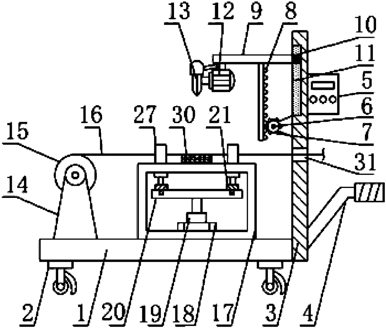
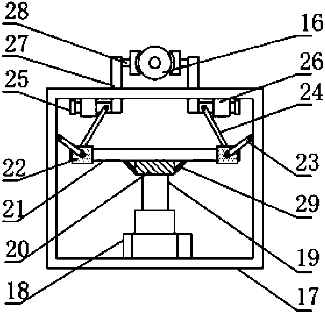
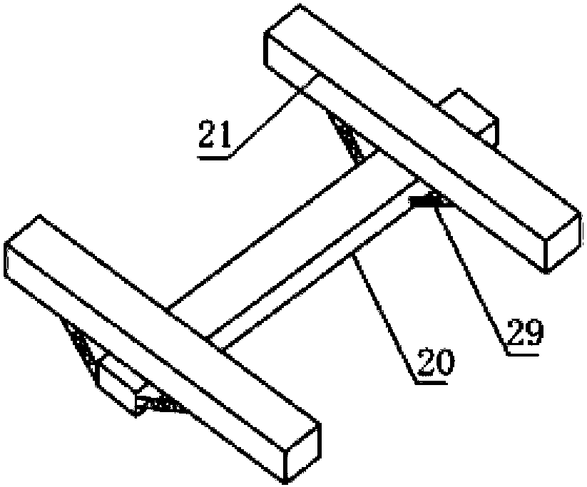
[0029] see Figure 1-6, the present invention provides a technical solution: a high-efficiency cutting device for steel wire rope processing, including a bottom plate 1, traveling wheels 2 are installed at the four corners of the bottom of the bottom plate 1, and brake plates are installed on the outer wall of the traveling wheels 2, so as to effectively improve the mobility of the device. A vertical board 3 is installed on the outer wall on the right side of ...


PUM


Abstract

The invention discloses an efficient cutting device for steel wire rope machining and a cutting method in the technical field of steel wire rope machining. The efficient cutting device comprises a bottom plate; a control switch is arranged at the top of the outer wall of the right side of a vertical plate; a pushing rod handle is arranged at the bottom of the outer wall of the right side of the vertical plate; the outer wall of the circumference of a gear is engaged with the inner wall of a tooth plate; a cutting motor is arranged at the left end of the bottom of a supporting plate; the outerwall of a roller is wound with steel wire ropes; a fixture box body is arranged on the right side of the top of the bottom plate; and a cutting table is arranged in the center of the top of the fixture box body. The efficient cutting device is simple to operate; clamping blocks are hinged with the two ends of each arc-shaped chuck, so that the efficient cutting device has movable activity, the steel wire ropes in different specifications are clamped conveniently, the more accurate location of the steel wire ropes is facilitated, and stress in every direction is kept uniformly; buffering columns are contacted with the steel wire ropes in advance, buffering springs contract due to the stress, so that a buffering effect is exerted, and bruise and damage on the surface of the steel wire ropesdue to the excessive stress are avoided; and two clamping plates are used for clamping the steel wire ropes, so that stable cutting of a cutting knife on the steel wire ropes is facilitated.

Description

technical field [0001] The invention relates to the technical field of steel wire rope processing, in particular to a high-efficiency cutting device and a cutting method for steel wire rope processing. Background technique [0002] The steel wire rope is a spiral steel wire bundle that twists the steel wires that meet the requirements of mechanical properties and geometric dimensions according to certain rules. The steel wire rope is composed of steel wire, rope core and grease. The rope core is the center, and a certain number of strands are twisted into a spiral rope. In material handling machinery, it is used for lifting, traction, tensioning and bearing. The steel wire rope has high strength, light weight, stable work, and is not easy to suddenly complete Breaks off and works reliably. [0003] In the process of steel wire rope processing and production, it is inevitable to cut the steel wire rope. In the Chinese application number CN201520680147.X, a steel wire rope cu...

Claims


Application Information

Patent Timeline
IPC IPC(8): B21F11/00B21F23/00
CPCB21F11/00B21F23/00
Inventor 许芳芳许凤珍
Owner 苏州斯强金属制品有限公司
Why Eureka
Try Eureka