
Laser calibrating method, machining method and device

A technology of laser processing method and calibration method, which is applied in the direction of laser welding equipment, metal processing equipment, manufacturing tools, etc., can solve the problems of reducing wafer yield, and achieve the effect of improving processing yield and quality, and precise alignment

Active Publication Date: 2018-08-17
深圳市大族半导体装备科技有限公司
View PDF6 Cites 10 Cited by
  • Summary
  • Abstract
  • Description
  • Claims
  • Application Information

AI Technical Summary

Problems solved by technology

[0003] Based on this, it is necessary to provide a laser calibration method, processing method and device that can improve the yield rate of wafers for the problem that traditional laser processing methods will reduce the yield rate of wafers

Method used


Image

  • Laser calibrating method, machining method and device
  • Laser calibrating method, machining method and device
  • Laser calibrating method, machining method and device

Examples


Embodiment Construction

[0038] In order to facilitate the understanding of the present invention, the present invention will be described more fully below with reference to the relevant drawings. The drawings show preferred embodiments of the present invention. However, the present invention can be implemented in many different forms and is not limited to the embodiments described herein. On the contrary, the purpose of providing these embodiments is to make the understanding of the disclosure of the present invention more thorough and comprehensive.

[0039] It should be noted that when an element is referred to as being "fixed to" another element, it can be directly on the other element or a central element may also exist. When an element is considered to be "connected" to another element, it can be directly connected to the other element or an intermediate element may be present at the same time. The terms "vertical", "horizontal", "left", "right" and similar expressions used herein are for illustr...


PUM


Abstract

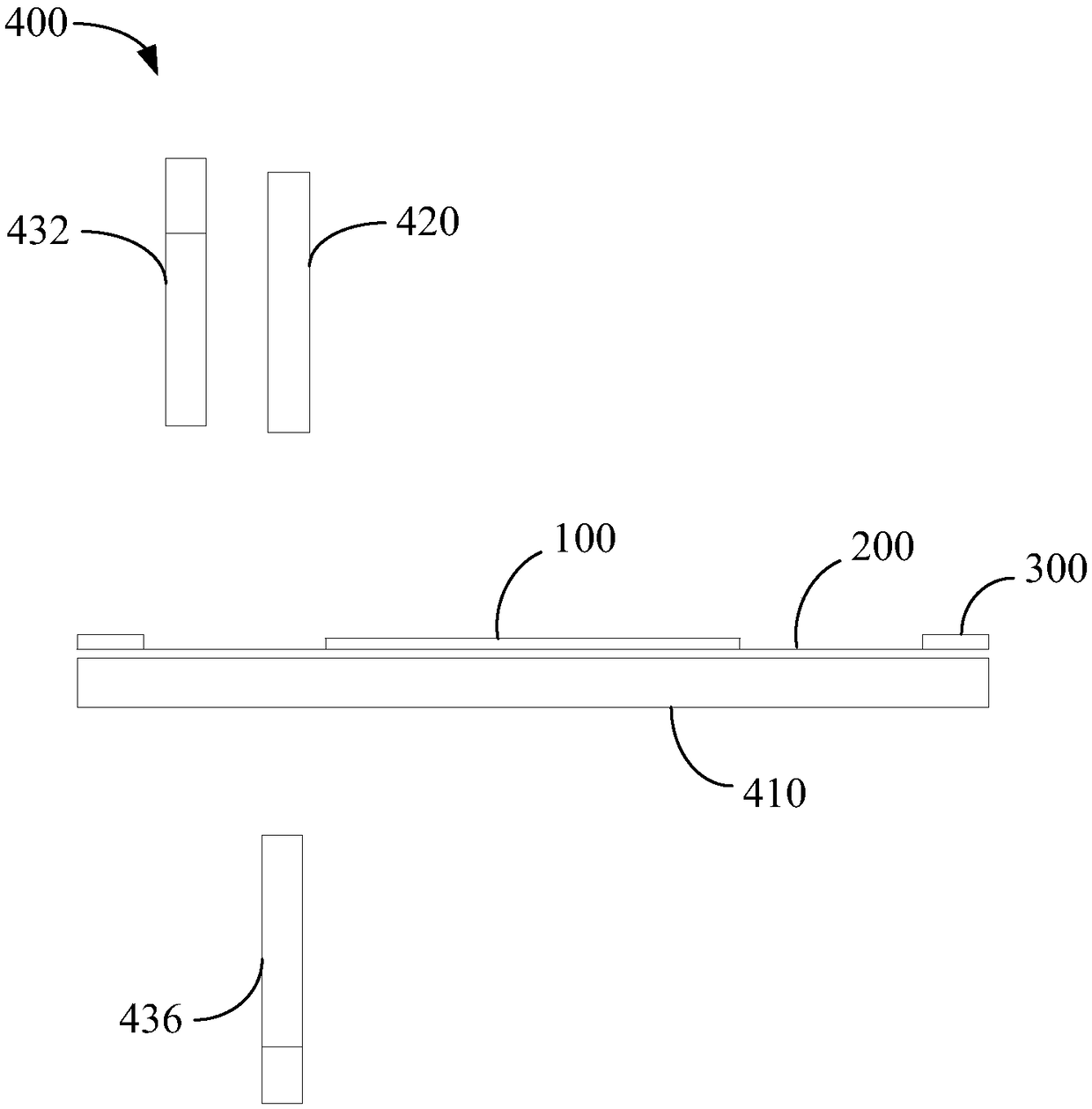
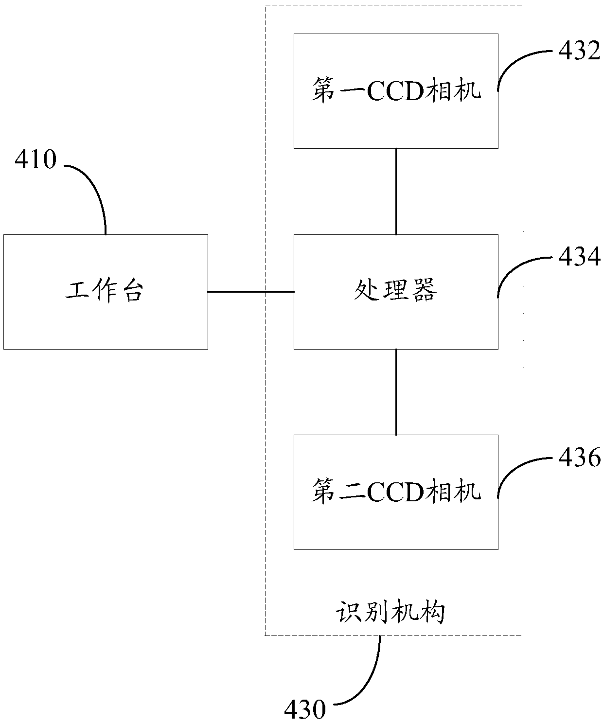
The invention relates to a laser calibrating method, machining method and device. The laser machining device comprises a worktable used for bearing a wafer assembly, a laser device and a recognition mechanism; when the laser machining device machines the wafer, the laser calibrating method is adopted to carry out first-time pre-calibrating, the worktable drives the wafer assembly to enter the cutting area from the calibrating area, the laser device cuts the front face of the wafer. The laser calibrating method mainly comprises the following steps that the laser device carries out ruling on thetransparent sticky film, and a test scratch is obtained; the worktable drives the wafer assembly to enter the calibrating area from the cutting area; the recognition mechanism obtains the image of the test scratch, and the deviation amount is determined; when the deviation amount is within the threshold value range, the worktable drives the wafer assembly to move, and the deviation amount is compensated for. Through the laser calibrating method, the machining position of the laser on the wafer assembly can be corrected, precise alignment of the laser and the wafer assembly can be achieved, and the machining yield of the wafer can be improved.

Description

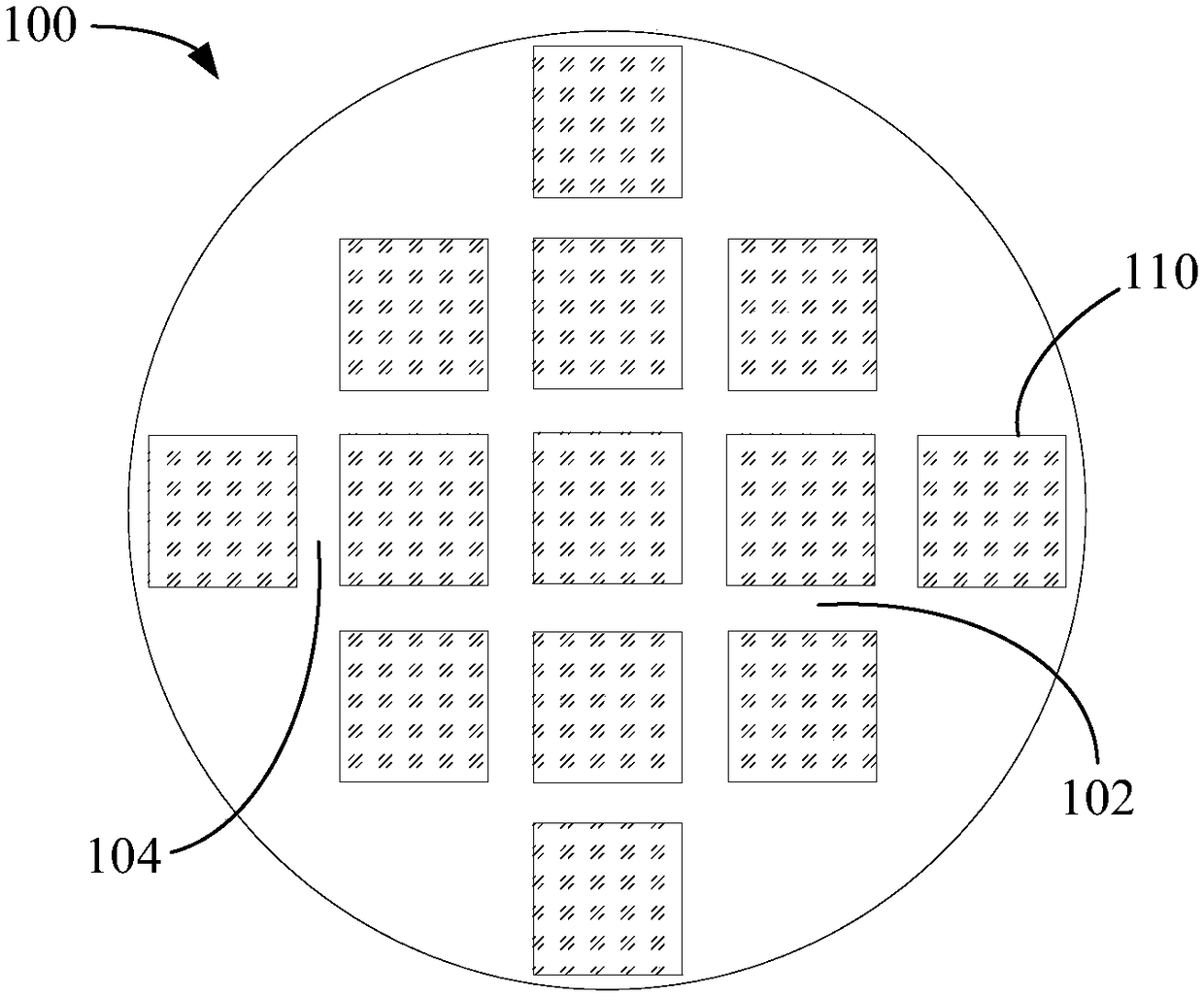
Technical field [0001] The invention relates to the technical field of laser processing, in particular to a laser calibration method, processing method and device. Background technique [0002] In the process of making semiconductor wafers, laser processing is generally used to cut a number of die units on the wafer. The die units and die units are separated by perpendicularly interlaced cutting lanes. These cutting paths are the cutting paths of the laser. Since the processing accuracy of the wafer is relatively high, the cutting lane needs to be aligned before laser cutting, so that the laser focus is aligned with the center of the cutting lane. Generally, after the alignment is determined, the same type of wafer can be processed, but due to various factors such as the external environment, the laser focus may deviate from the center of the dicing lane, which reduces the yield of the wafer. Summary of the invention [0003] Based on this, it is necessary to provide a laser cal...

Claims


Application Information

Patent Timeline
Patent Type & Authority Applications(China)
IPC IPC(8): B23K26/042B23K26/38B23K101/40
CPCB23K26/042B23K26/38
Inventor 冯雷张红江周欢黄嘉杨金虎刘勇辉吴凡曾威尹建刚高云峰
Owner 深圳市大族半导体装备科技有限公司
Learn More