Laser light positioning and machining machine tool

A technology for processing machine tools and laser light, applied in metal processing mechanical parts, positioning devices, metal processing equipment, etc., can solve the problems of low cost performance, high cost of cutting machines, inability to realize processing methods, etc., to achieve accurate processing, simple and convenient operation , The effect of feeding is simple and convenient

Inactive Publication Date: 2018-08-17
HENAN MECHANICAL & ELECTRICAL VOCATIONAL COLLEGE
View PDF6 Cites 3 Cited by
  • Summary
  • Abstract
  • Description
  • Claims
  • Application Information

AI Technical Summary

Problems solved by technology

[0004] The second is a large-scale laser cutting machine. This kind of cutting machine has precise positioning and completes the cutting process through the rotation of the worktable without frequent handling of plates. However, this kind of cutting machine is expensive and

Method used


Image

  • Laser light positioning and machining machine tool
  • Laser light positioning and machining machine tool
  • Laser light positioning and machining machine tool

Examples


Embodiment Construction

[0019] In order to understand the above-mentioned purpose, features and advantages of the present invention more clearly, the present invention will be further described in detail below in conjunction with the accompanying drawings and specific embodiments. It should be noted that, in the case of no conflict, the embodiments of the present application and the features in the embodiments can be combined with each other.

[0020] In the following description, many specific details are set forth in order to fully understand the present invention. However, the present invention can also be implemented in other ways different from those described here. Therefore, the protection scope of the present invention is not limited by the specific details disclosed below. EXAMPLE LIMITATIONS.

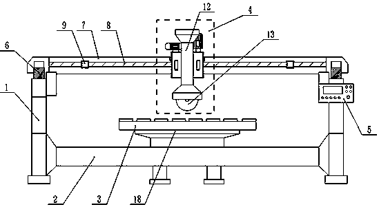
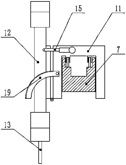
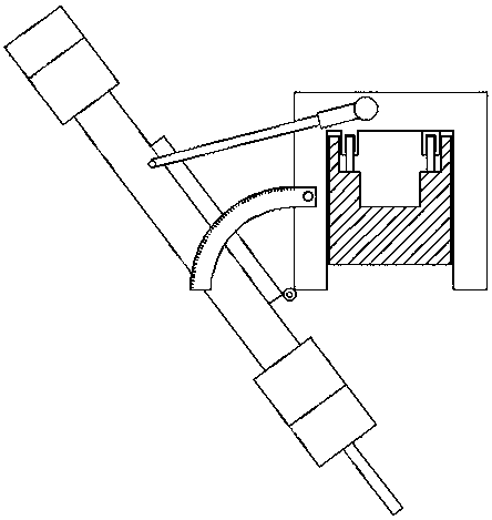
[0021] Such as Figure 1~Figure 3 As shown, the laser positioning processing machine tool of the present invention comprises a frame, an electric control panel 5 installed on the frame, a workbench ...


PUM

PropertyMeasurementUnit
Rotation angleaaaaaaaaaa

Abstract

The invention provides a laser light positioning and machining machine tool. The laser light positioning and machining machine tool comprises a rack; the rack comprises a stand rack body and a transverse rack body; a longitudinal crossbeam guide track is disposed above the stand rack body; a crossbeam longitudinally moves on the crossbeam guide track; a machining table guide track is disposed above the crossbeam, a machining table transversely moves on the machining table guide track; the machining table comprises a sliding frame; a machine head capable of ascending or descending vertically isfixed to the front of the sliding frame; and an inclining device is disposed between the machine head and the sliding frame and controls the machine head inclined relative to the vertical plane. Thelaser light positioning and machining machine tool is fully automatically controlled and easy to operate, laser light positioning and machining are accurate, the working table rotates by 360 degrees,plates do not need to be moved and calibrated in the machining process, time and labor are saved, the working table can turn over, then feeding is simple and convenient, the machine head can incline,multi-functional application of plate cutting, chamfering, edge grinding and the like is achieved, and the machine tool is practical.

Description

technical field [0001] The invention relates to the technical field of electromechanical equipment, in particular to a laser light positioning processing machine tool. Background technique [0002] Cutting machine is a common equipment in the field of mechanical processing. The common types of cutting machines include flame cutting machine, laser cutting machine, water cutting machine and so on. In stone processing, there are two common processing equipment: [0003] One is a small water cutting machine. This kind of cutting machine is positioned by a ruler, and the processing accuracy is low. Because the positioning direction is fixed, the cutting can only be completed by continuously moving and moving the plate during the cutting process. It is not only time-consuming and laborious, but also easy to damage the plate. Error; the advantage is that it is easy to use, can replace a variety of tools, and complete various processing methods such as edging and chamfering. [00...

Claims


Application Information

Patent Timeline
IPC IPC(8): B23Q1/52B23Q3/04B23Q17/24
CPCB23Q1/52B23Q3/04B23Q17/2419
Inventor 赵霞台畅白小海连瑞瑞李海敏
Owner HENAN MECHANICAL & ELECTRICAL VOCATIONAL COLLEGE
Why Eureka
Try Eureka