Polishing device for automobile parts

A technology for auto parts and bevel gears, which is applied in the direction of grinding drive devices, grinding/polishing safety devices, grinding machines, etc. It can solve the problem of reducing the service life of mounting parts, easily hurting the hands of installers, and increasing wear of mounting parts, etc. problem, to achieve the effect of improving work efficiency

Active Publication Date: 2018-08-17
涟源市普东汽车配件铸造有限公司
View PDF6 Cites 3 Cited by
  • Summary
  • Abstract
  • Description
  • Claims
  • Application Information

AI Technical Summary

Problems solved by technology

These punching methods are all rough machining, so many metal burrs or plastic burrs will be left on the punched holes. No matter what kind of burrs are easy to scratch the accessory packaging bag, and it is easy to hurt the hands of the installer, so it is necessary to Deal with the remaining burrs after drilling to avoid the above problems
[0003] The existing burr treatment methods are mechanical or manual grinding. However, both grinding methods are used to polish the surface of the accessories, which can only clean the burrs on the surface of the accessories. In fact, the bottom surface of the accessories and the inside of the drilled hole There are still many glitches that are not handled well
When the mounting part passes through the hole for accessories installation, the burrs may increase the resistance of the mounting part and increase the wear of the mounting part, thereby reducing the service life of the mounting part. If the burrs on the bottom surface are not well treated, it will also affect the appearance of the accessories

Method used


Image

  • Polishing device for automobile parts
  • Polishing device for automobile parts
  • Polishing device for automobile parts

Examples


Embodiment

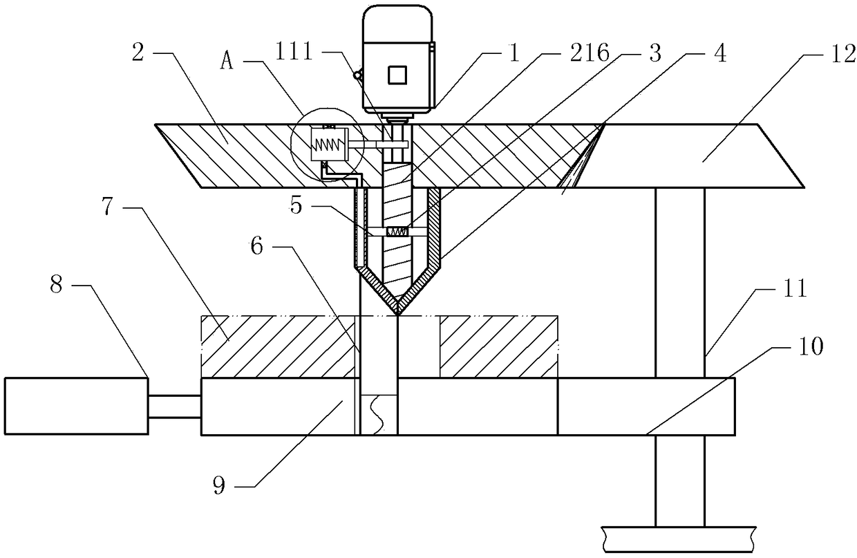
[0023] as attached figure 1 And attached figure 2 As shown, a grinding device for auto parts includes a frame and a motor 1, the motor 1 is fixed on the frame and the output shaft of the motor 1 faces downward, the output shaft of the motor 1 is fixed with a main bevel gear 2 and is located at the main bevel Cam 111 in gear 2.

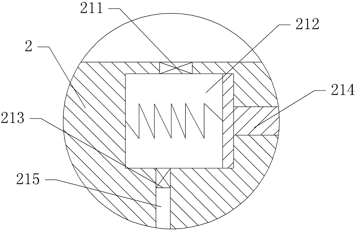
[0024] The bottom of the main bevel gear 2 is provided with a support shaft 216, and the two sides of the support shaft 216 are provided with friction plates 4 slidingly connected with the main bevel gear 2. The two friction plates 4 are arc-shaped and form a drum. The friction plate 4 is bonded with sandpaper by glue. The support shaft 216 is provided with a slideway, and the friction plates 4 are fixed with bumps 5 located in the slideway, and a compression spring 3 is fixed between the two bumps 5 . The friction plate 4 on the left side is provided with an inner chamber, and the left side wall of the inner chamber is provided with a through hole...


PUM


Abstract

The invention relates to the technical field of machining of automobile parts, and discloses a polishing device for automobile parts. The polishing device comprises a rack and a motor, and a main bevel gear is fixed to an output shaft of the motor; a supporting shaft is arranged at the bottom of the main bevel gear, friction plates slidably connected with the main bevel gear are arranged on the two sides of the supporting shaft, and protruding blocks are fixed to the friction plates correspondingly; a compressed spring is fixed between the protruding blocks, and the bottoms of the friction plates are both bevels inclined towards the supporting shaft; the lower portion of the main bevel gear is further provided with a telescopic air cylinder and a supporting seat; the supporting seat comprises a fixed seat body and a sliding seat body, a telescopic rod of the telescopic air cylinder is fixedly connected with the sliding seat body, the sliding seat body is slidably connected with a positioning rod matched with the friction plates, and the bottom of the positioning rod is provided with a reset spring; and the rack is rotatably connected with a secondary bevel gear which is engaged with the main bevel gear, the rack is provided with a lead screw, the secondary bevel gear drives the lead screw to rotate, and a nut seat of the lead screw is fixedly connected with the fixed seat body.According to the polishing device for the automobile parts, the structure is simple, and part holes and the bottom faces of the parts can be polished and deburred.

Description

technical field [0001] The invention relates to the technical field of auto parts processing, in particular to a grinding device for auto parts. Background technique [0002] During the processing of auto parts, some accessories such as mounting plates, wind deflectors, brackets and main boards need to be punched. The holes are all for the convenience of installation. There are many ways to punch holes, such as drill drilling, stamping Punching etc. These punching methods are all rough machining, so many metal burrs or plastic burrs will be left on the punched holes. No matter what kind of burrs are easy to scratch the accessory packaging bag, and it is easy to hurt the hands of the installer, so it is necessary to Deal with the remaining burrs after drilling to avoid the above problems. [0003] The existing burr treatment methods are mechanical or manual grinding. However, both grinding methods are used to polish the surface of the accessories, which can only clean the b...

Claims


Application Information

Patent Timeline
Patent Type & Authority Applications(China)
IPC IPC(8): B24B9/00B24B27/00B24B47/12B24B47/16B24B55/06
CPCB24B9/00B24B27/0076B24B47/12B24B47/16B24B55/06
Inventor 王作栋
Owner 涟源市普东汽车配件铸造有限公司
Why Eureka
Try Eureka