
A method for robot self-calibration

A robot and self-calibration technology, applied in manipulators, program-controlled manipulators, manufacturing tools, etc., can solve the problems of harsh conditions, increase the difficulty of calibration experiments, and affect the calibration accuracy, and achieve low cost, reduce difficulty, and improve calibration accuracy. Effect

Active Publication Date: 2021-03-16
JIANGNAN UNIV
View PDF6 Cites 2 Cited by
  • Summary
  • Abstract
  • Description
  • Claims
  • Application Information

AI Technical Summary

Problems solved by technology

There is a common problem between the first two calibration methods: what method to use to accurately measure, identify and compensate the error parameters
For example, the error model calibration method is established by using the projections of any two points on the plane normal vector to be equal. This method puts forward requirements for the positioning of the calibration block. It is necessary to ensure that the plane normal vectors are parallel to the robot base coordinate system, and the conditions are too strict. This greatly increases the difficulty of the calibration experiment; in addition, some scholars propose to establish an error model based on the fitted plane of each terminal position data. Although there is no requirement for the placement of the calibration block, there is a certain gap between the fitted plane and the actual constrained plane. Deviation, which will directly affect the calibration accuracy

Method used


Image

  • A method for robot self-calibration
  • A method for robot self-calibration
  • A method for robot self-calibration

Examples


Embodiment 1

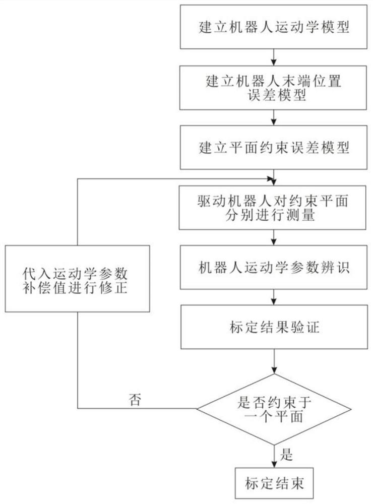
[0058] Such as figure 1 Shown is a schematic flow chart of the robot self-calibration method based on the plane constraint error model described in the first embodiment of the present invention. The so-called calibration is to use advanced measurement means and appropriate parameter identification methods to identify the accurate parameters of the robot model, thereby improving Process with robotic precision. In order to solve the problems of high cost of measuring instruments, complicated installation and operation, professional and technical personnel are required to operate these instruments, and the space position of the calibration block is demanding.

[0059] This embodiment provides a robot self-calibration method based on a plane-constrained error model, which utilizes the establishment of a plane-constrained error model to self-calibrate the robot. The measurement of kinematic parameters is usually identified by internal sensor data and external measurement device dat...


PUM


Abstract

The invention discloses a plane constraint error model and a robot self-calibration method. The method comprises the following steps of 1, establishing a robot kinematics model; 2, establishing a robot tail end position error model; 3, establishing the plane constraint error model; 4, driving a robot to measure the constraint plane; 5, identifying kinematics parameters of the robot; and 6, verifying the calibration result. The plane constraint error model and the self-calibration method have the beneficial effects that firstly, cost is low, wherein one calibration block with relatively high precision is needed, and cost not exceeds one thousand while the advanced measuring equipment tends to be tens of thousands or more millions in cost; secondly, a plane accurate spatial equation can be obtained, compared with a traditional plane constraint calibration method, the calibration precision is improved; thirdly, compared with a traditional plane constraint error model, the error model is greatly simplified; and fourthly, the calibration block can be placed in the working space of the robot in any posture, and the difficulty of calibration experiments is reduced.

Description

technical field [0001] The invention relates to the technical field of calibration of industrial robots, in particular to a robot self-calibration method. Background technique [0002] Although industrial robots have high repeatability in recent years, their precision has been poor. For robots without calibration, the accuracy error can reach several millimeters. Therefore, precise calibration of the robot is necessary in many applications. The so-called calibration is the process of using advanced measurement methods and appropriate parameter identification methods to identify the exact parameters of the robot model, thereby improving the accuracy of the robot. Robot calibration technology can be divided into three different levels: the first level is the joint level, the purpose is to correctly determine the relationship between the joint sensor value and the actual joint value; the second level is to calibrate the complete robot kinematics model, including describing th...

Claims


Application Information

Patent Timeline
Patent Type & Authority Patents(China)
IPC IPC(8): B25J9/16B25J9/10
CPCB25J9/10B25J9/16
Inventor 王晨学平雪良徐超蒋毅
Owner JIANGNAN UNIV
Learn More