Vertical type silicon wafer magnetron sputtering film plating machine

A technology of magnetron sputtering and coating machine, which is applied in sputtering coating, vacuum evaporation coating, ion implantation coating, etc. It can solve the problems of uneven coating, large size of silicon wafer placement board, and high failure rate of equipment. Achieve the effect of improving coating quality, good vacuum effect and low failure rate

Active Publication Date: 2018-08-17
湖南众源科技有限公司 +1
View PDF13 Cites 6 Cited by
  • Summary
  • Abstract
  • Description
  • Claims
  • Application Information

AI Technical Summary

Problems solved by technology

[0002]Vertical magnetron sputtering coating machine for silicon wafers is used to coat silicon wafers with one or more layers of metal films using magnetron sputtering targets in a vacuum environment , the silicon wafer placement plate that hangs the silicon wafers moves in the vacuum chamber using a transmission device. The top of the conventional transmission track is flat, and the silicon wafer placement plate is directly placed on the track to move. In order to maintain balance, both the track and the silicon wafer placement plate must be designed Wider, the width of the vacuum chamber must also be designed wider, so that the volume of the vacuum chamber increases, the vacuum effect is not good, and the coating effect is affected; there is also a problem that the entire silicon wafer needs to be placed and removed. The placing plate is taken out from the vacuum chamber, which is inconvenient when the size of the silicon wafer placing plate is large
[0003]In addition, there are generally gas residues or other stains attached to the silicon wafer. If the stains are not removed during coating, the coating will be uneven, and the quality of the resulting film will be poor. , the ionization electrode can be used to ionize the gas to clean the surface of the silicon wafer. However, the traditional design of the ion cleaning electrode does not have a good heat dissipation effect and the equipment failure rate is high.

Method used


Image

  • Vertical type silicon wafer magnetron sputtering film plating machine
  • Vertical type silicon wafer magnetron sputtering film plating machine
  • Vertical type silicon wafer magnetron sputtering film plating machine

Examples


Embodiment Construction

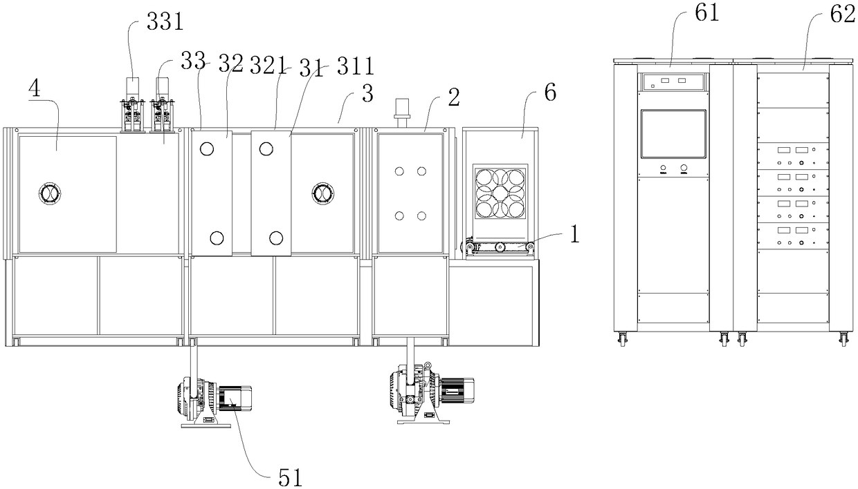
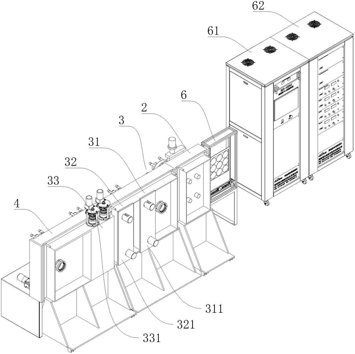
[0030] Such as Figure 1-Figure 6 Shown is a kind of vertical magnetron sputtering coating machine for silicon wafers of the present invention, comprising: a vacuum chamber, a transmission device 1 arranged in the vacuum chamber for suspending and moving silicon wafers, and a vacuum pumping system and a power control system;

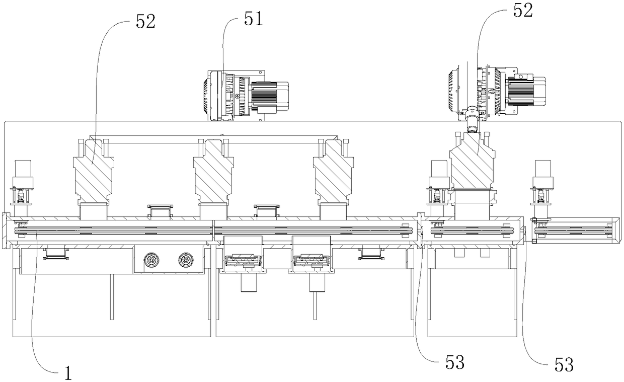
[0031] Such as Figure 5-Figure 6 As shown, the transmission device 1 includes a silicon wafer hanging plate 13, a hanging plate base 14, and a rail car 15 arranged in a vacuum chamber. The silicon wafer hanging plate 13 and the hanging plate base 14 are detachably connected; The bottom of the hanging board base 14 is provided with a protrusion, and the hanging board base 14 is fixedly plugged with the rail car 15 through the cooperation of the protrusion and the groove.

[0032] Wherein, the groove includes a first groove 151 arranged in the middle position of the top of the rail car 15 and a plurality of second grooves 152 arranged on both sides of th...


PUM


Abstract

The invention discloses a vertical type silicon wafer magnetron sputtering film plating machine. The vertical type silicon wafer magnetron sputtering film plating machine comprises a vacuum chamber, atransmission device, a vacuum-pumping system and a power supply control system, wherein the transmission device is arranged in the vacuum chamber and is used for hanging and moving silicon wafers, the vacuum-pumping system is used for carrying out vacuumizing, and the power supply control system is used for supplying power and controlling a working condition; the vacuum chamber comprises a washing chamber and a sputtering chamber which are hermetically connected mutually, an ion cleaning electrode is arranged in the washing chamber, and a sputtering target is arranged in the sputtering chamber; the transmission device comprises a silicon wafer hanging plate, a hanging plate base and a rail car which are arranged in the vacuum chamber, the silicon wafer hanging plate is detachably connected with the hanging plate base, a groove is formed in the top of the rail car, a bulge portion is formed on the bottom of the hanging plate base, and the hanging plate base is in fixed inserting connection with the rail car through the matching between the bulge portion and the groove. By adopting the design, the volume of the vacuum chamber can be reduced, the vacuum effect is good, the silicon wafers are conveniently picked and placed, residues can be effectively removed from surfaces of the silicon wafers, the silicon wafers can be effectively heated, and film-plated wafers are good in effect.

Description

technical field [0001] The invention relates to the field of vacuum coating, in particular to a vertical magnetron sputtering coating machine for silicon wafers. Background technique [0002] The vertical magnetron sputtering coating machine for silicon wafers is used to coat silicon wafers with one or more layers of metal film using magnetron sputtering targets in a vacuum environment. To move, the top of the conventional transmission track is flat, and the silicon wafer placement plate is directly placed on the track to move. In order to maintain a balance, both the track and the silicon wafer placement plate must be designed wider, resulting in a wider width of the vacuum chamber. In this way, the volume of the vacuum chamber increases, and the vacuum effect is not good, which affects the coating effect; there is also a problem that the entire silicon wafer placement plate needs to be taken out from the vacuum chamber to place the silicon wafer and take the silicon wafer....

Claims


Application Information

Patent Timeline
IPC IPC(8): C23C14/35C23C14/02C23C14/56
CPCC23C14/021C23C14/35C23C14/568Y02P70/50
Inventor 李纲周通之隆组义罗立珍
Owner 湖南众源科技有限公司
Why Eureka
Try Eureka