
Piston combustor structure

A combustion chamber and piston technology, applied in the field of piston combustion chamber structure, can solve problems such as increased fuel consumption, difficult combustion control, insufficient combustion, etc., and achieve the effect of reducing fuel consumption and combustion noise

Pending Publication Date: 2018-08-17
JIANGSU SIDA POWER MECHANICAL GROUP
View PDF7 Cites 2 Cited by
  • Summary
  • Abstract
  • Description
  • Claims
  • Application Information

AI Technical Summary

Problems solved by technology

[0004] Most engine piston combustion chambers use ω-shaped combustion chambers. Disadvantages: the intake vortex is too strong, and in a short period of time, the fuel oil sprayed by the injector is unevenly mixed with fresh air, and the combustion is not complete. It is also difficult to control within the range, resulting in increased emissions of NOx, PM, etc., and increased fuel consumption

Method used


Image

  • Piston combustor structure
  • Piston combustor structure
  • Piston combustor structure

Examples


Embodiment Construction

[0022] The present invention will be further described below in conjunction with specific drawings.

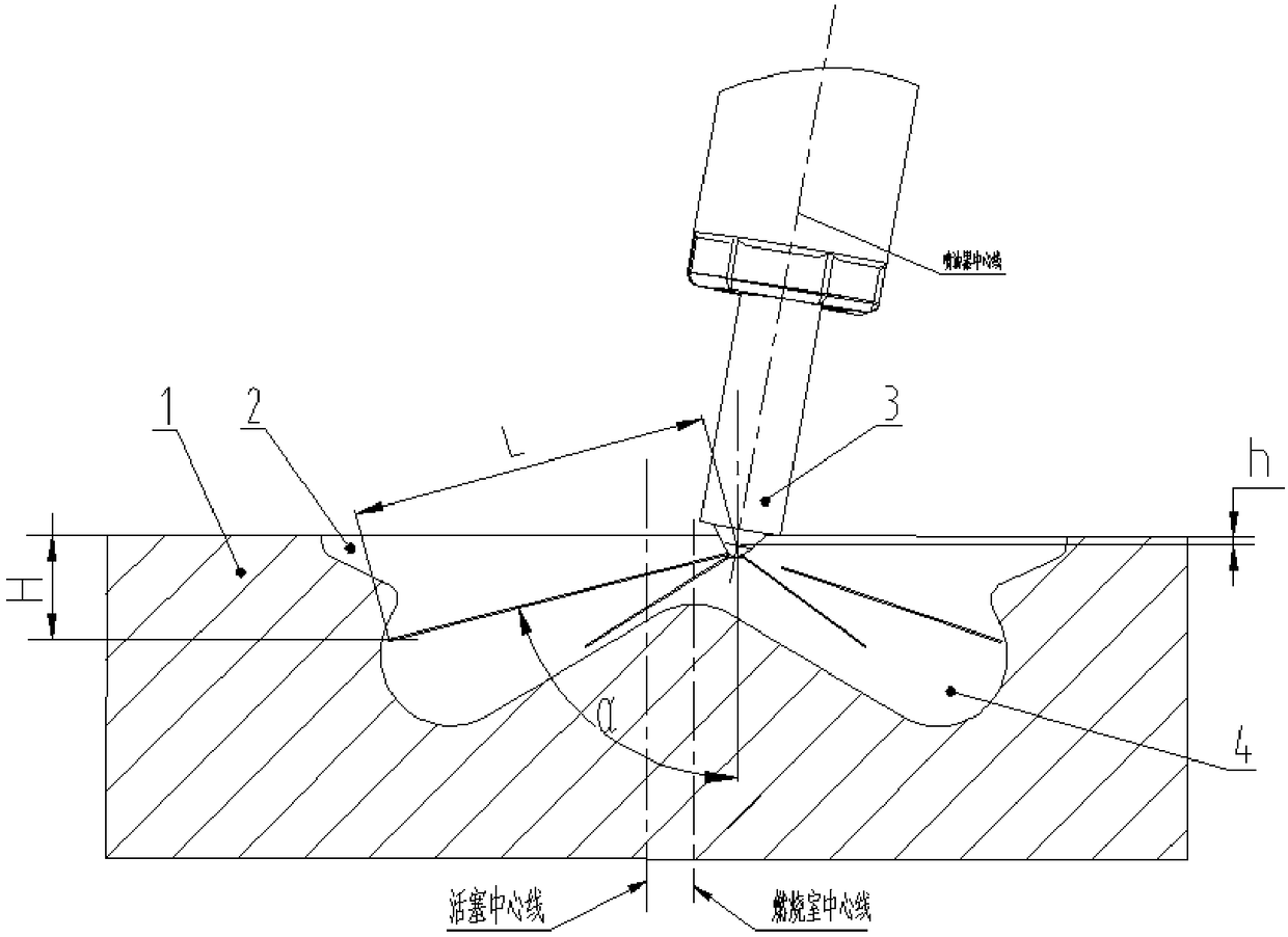
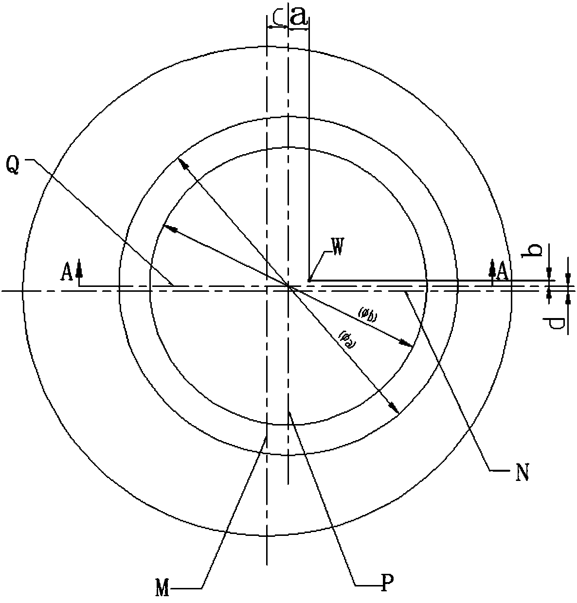
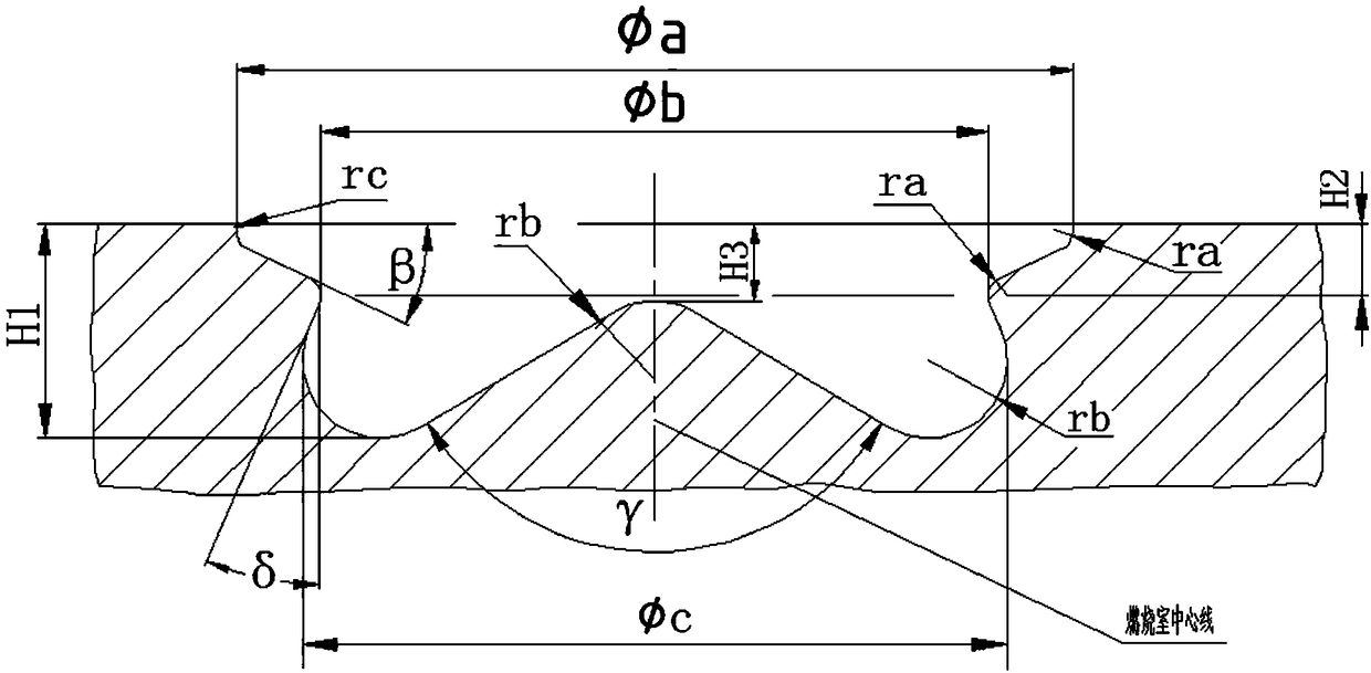
[0023] Such as Figure 1-3 Shown, a kind of piston combustion chamber structure is characterized in that, provides a kind of piston combustion chamber structure, is characterized in that, comprises piston 1, and the center line of piston is as figure 1 As shown, the upper part of the shallow basin type combustion chamber 2, when the piston moves up to near the top dead center, prevents the oil spray from splashing on the cylinder wall and the top surface of the piston; the upper part is a shallow basin type combustion chamber. A tumble flow is formed around the combustion chamber, which is helpful for mixing and combustion. The shallow basin type combustion chamber opening and the rounded corner R at the bottom can effectively avoid thermal stress.

[0024] The lower part of the ω-shaped combustion chamber 4, the two are combined by the position of the injector 3 and the posi...


PUM


Abstract

The invention relates to the field of technical schemes and structures of internal combustion engines, in particular to a piston combustor structure. The piston combustor structure comprises a shallow-basin-shaped combustor on theupper portion and a w-shaped combustor on the lower portion. The shallow-basin-shaped combustor and the w-shaped combustor are combined through the position of an oil atomizer and the position of an oil line. The shallow-basin-shaped combustor is in transition to the w-shaped combustor through a taper face angle beta, an orifice of the w-shaped combustor is connectedwith the shallow-basin-shaped combustor through a taper face angle delta, a transition area therebetween is convergent, and the distance h between the center of an oil beam of theoil atomizer and thetop face of a piston is controlled to be 1.1-1.5 mm. The advantages and benefits of the shallow-basin-shaped combustor and the w-shaped combustor are brought into play due to ingenious combination ofthe shallow-basin-shaped combustor with the w-shaped combustor. An expected mixing effect and requirements of fuel oil entering a cylinder and fresh air entering the cylinder are achieved, the combustion rate and temperature can be controlled, and the emission quantity of nitrogen oxide and PM particles is controlled.

Description

technical field [0001] The invention relates to a new type of piston combustion chamber technical scheme, which is used for the structural design of the piston combustion chamber of diesel engines with national five and above emission regulations, and the mutual matching between fuel injectors, which belongs to the technical scheme and structure field of internal combustion engines, specifically It is a piston combustion chamber structure. Background technique [0002] In recent years, due to the improvement of the technical level of the engine, the performance indicators have been continuously strengthened, the reliability has been improved, and the emission requirements have become more and more stringent. The mixing and combustion of fuel and fresh impulse directly affect the engine's emissions, performance, fuel consumption, noise, reliability and many other aspects. [0003] With the development and progress of society, human beings have higher and higher requirements ...

Claims


Application Information

Patent Timeline
Patent Type & Authority Applications(China)
IPC IPC(8): F02B23/06F02F3/26F02M61/14
CPCF02B23/0672F02F3/26F02M61/14Y02T10/12
Inventor 龚灵辉沈黎明
Owner JIANGSU SIDA POWER MECHANICAL GROUP
Features
  • Generate Ideas
  • Intellectual Property
  • Life Sciences
  • Materials
  • Tech Scout
  • Unparalleled Data Quality
  • Higher Quality Content
  • 60% Fewer Hallucinations
Learn More