High speed rotating shafting dynamic radial loading stiffness test method and device

A high-speed rotating shaft and testing device technology, which is applied in the direction of measuring devices, testing of mechanical components, testing of machine/structural components, etc., can solve the problems of limited loading force, limited by vibration, difficult to accurately calibrate, etc., and achieve stable linear loading , non-linear, easy-to-load effects

Active Publication Date: 2018-08-17
HUNAN UNIV
View PDF8 Cites 2 Cited by
  • Summary
  • Abstract
  • Description
  • Claims
  • Application Information

AI Technical Summary

Problems solved by technology

Its disadvantages are: a. The stiffness of the air bearing is small and the loading force is limited; b. The air bearing measuring device takes up a lot of space, which is restricted by the space at the extension end of the spindle; c. It is difficult to keep the air during the loading process. In the floating state, the thickness of the air film is only on the order of microns. During the loading process, it is easy to cause collision accidents between the air film bearing and the measured surface of the spindle due to loading bias.
[0005] 2. Non-contact liquid suspension loading measuring device, its loading capacity is higher than that of air floating loading, but the structure is complex, prone to liquid leakage, limited by the loading space, only applicable to specific test spindles
The disadvantages of this method are: (1) It can only measure the stiffness in the vertical direction; (2) When the spindle size is large, the bearing size is large and limited by vibration, it is only suitable for use when the spindle speed is low
The disadvantages of this method are: (1) the loading bearing rotates with the main shaft at high speed, the noise and vibration are large, and the loading bearing is easily heated and damaged; (2) the bearing and the outer circle of the main shaft are in smooth normal contact, and the position of the loading contact point Prone to drift, resulting in inaccurate test results
[0009] 6. The one-way electromagnetic loading measuring device has the disadvantages that (1) the electromagnetic force has a nonlinear relationship with the journal displacement, which is difficult to calibrate accurately, and errors are prone to occur in the test results; (2) when the measured surface is not magnetically conductive , the measurement method is not applicable; (3) The bearing and the outer circle of the main shaft are in smooth normal contact, and the position of the loading contact point is prone to shift, resulting in inaccurate test results; (4) When the distance between the magnetic bearing stator and the rotor surface is close , due to the rapid increase of electromagnetic suction, it is easy to cause adhesion, and in the state of high-speed rotation of the spindle, it is easy to cause friction, heat, burnout and even safety accidents

Method used


Image

  • High speed rotating shafting dynamic radial loading stiffness test method and device
  • High speed rotating shafting dynamic radial loading stiffness test method and device
  • High speed rotating shafting dynamic radial loading stiffness test method and device

Examples


Embodiment 1

[0043] The implementation steps of the dynamic radial loading stiffness testing method of the high-speed rotating shaft system in this embodiment include:

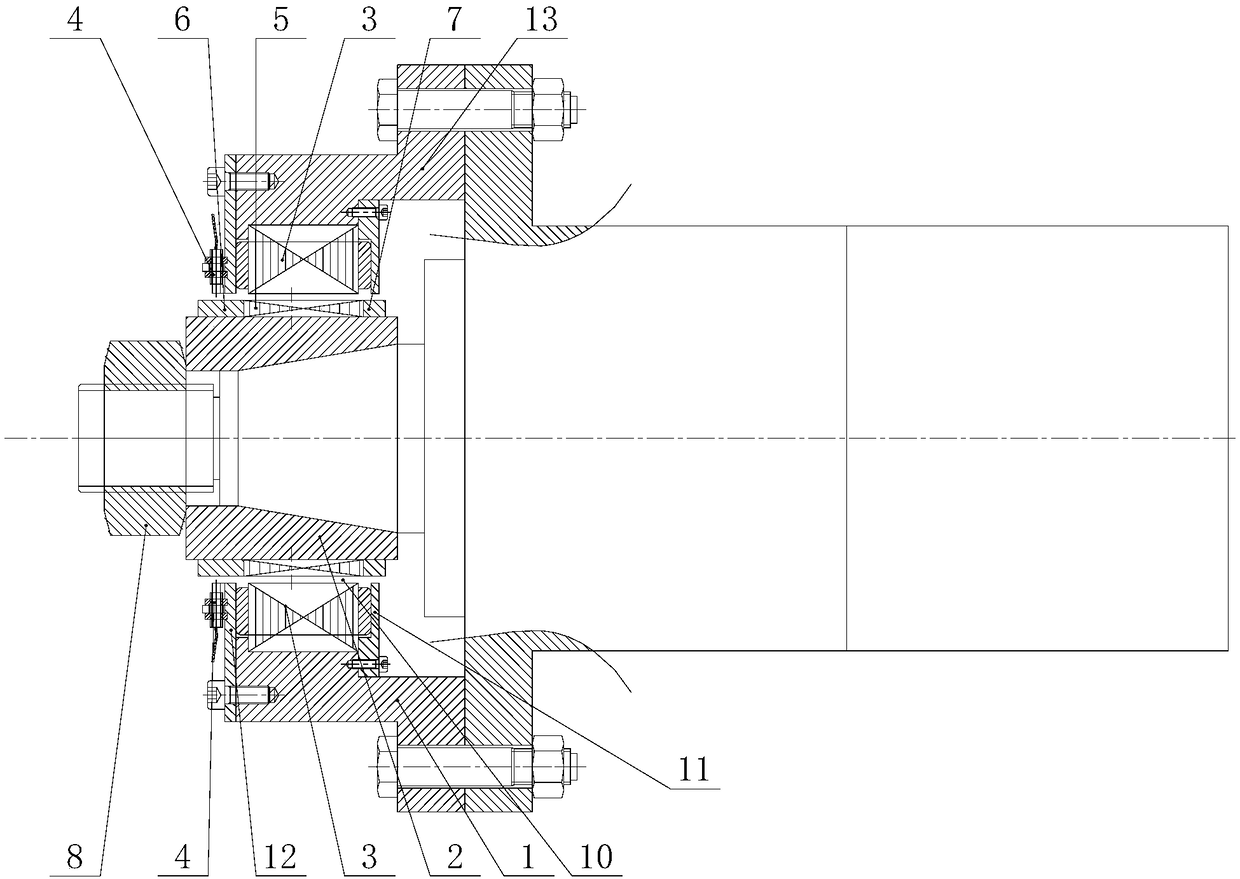
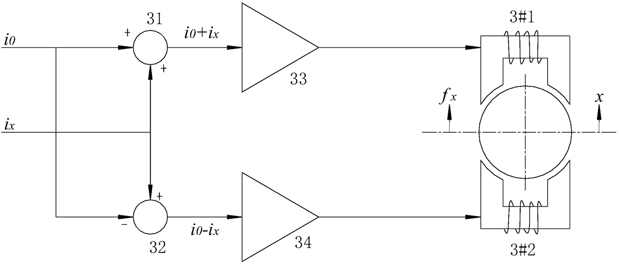
[0044] 1) Install the rotor on the rotating shaft of the high-speed rotating shaft system under test in advance, install two electromagnetic windings for applying radial magnetic attraction force to the rotating shaft through the rotor on the flange, and at least one for detecting the radial displacement of the rotating shaft Displacement sensor, the two electromagnetic windings are arranged symmetrically with respect to the rotor; the drive current output to one electromagnetic winding during the test is i 0 + i x , the driving current output to another electromagnetic winding is i 0 -i x , where i 0 is the reference current, i x In order to control the current, record the change of the driving current over time and the radial displacement output by the displacement sensor, and jump to the next step;

[0045] 2) Dete...

Embodiment 2

[0065] This embodiment is basically the same as Embodiment 1, and the main difference is that in step 4), only the Fourier transform result of the radial magnetic attraction applied to the rotating spindle and the Fourier transform result of the radial displacement of the rotating spindle are calculated. The ratio between is output as the second dynamic stiffness obtained from the test. The function expression for calculating the second dynamic stiffness is shown in formula (2):

[0066]

[0067]

[0068]

[0069] In formula (2), K(ω) is the second dynamic stiffness (quantity that varies with frequency), F(ω) is the Fourier transform result of the radial magnetic attraction force f(t) applied to the rotating spindle, and X( ω) is the Fourier transform result of the radial displacement x(t) of the rotating spindle, f(t) is the radial magnetic attraction force applied to the rotating spindle, x(t) is the radial displacement of the rotating spindle, and t is time .

Embodiment 3

[0071] This embodiment is basically the same as Embodiment 1, and the main difference is that in step 1), not only the ratio between the radial magnetic force applied to the rotating spindle and the radial displacement of the rotating spindle is calculated as the first dynamic stiffness output obtained from the test At the same time, the ratio between the Fourier transform result of the radial magnetic attraction force applied to the rotating spindle and the Fourier transform result of the radial displacement of the rotating spindle is calculated as the second dynamic stiffness output obtained from the test. The second dynamic stiffness For the calculation details, please refer to Example 2.


PUM


Abstract

The invention discloses a high speed rotating shafting dynamic radial loading stiffness test method and device. The method comprises the steps that driving current is outputted to electromagnetic windings; the driving current and the radial displacement outputted by a displacement sensor are recorded; the radial displacement of the rotating spindle and the radial magnetic attraction force appliedto the rotating spindle are determined; and the specific value of the radial magnetic attraction force applied to the rotating spindle to the radial displacement of the rotating spindle is calculatedas the first dynamic stiffness and/or the specific value of the Fourier transform results of the radial magnetic attraction force and the radial displacement is calculated as the second dynamic stiffness. The device comprises a stator fixing base and a rotor clamp. An accommodating hole, the displacement sensor and two electromagnetic windings symmetrically arranged relative to the rotor clamp arearranged on the stator fixing base. The rotor clamp is arranged in the accommodating hole. The external wall of the rotor clamp is provided with a silicon steel rotor which is arranged between the two electromagnetic windings. The method and the device have the advantages of being high in measurement accuracy, high in applicability, convenient to measure and low in energy consumption and can realize stable linear loading.

Description

technical field [0001] The present invention relates to the dynamic stiffness testing technology of high-speed machine tool spindles, high-speed electric spindles and high-speed motors, in particular to a method and device for testing the dynamic radial loading stiffness of high-speed rotating shafts, which are used to complete the radial stiffness of high-speed electric spindles and high-speed motors. Contact loading and dynamic stiffness testing. Background technique [0002] The high-speed machine tool spindle is the core functional component of a modern machine tool. Its function is to drive the tool (grinding wheel) or workpiece to rotate to achieve high-speed precision machining. With the continuous improvement of modern industry's requirements for machining accuracy and machining efficiency of machine tools, machine tools have higher and higher requirements for spindle performance. Rigidity is one of the important indicators to measure the performance of high-speed m...

Claims


Application Information

Patent Timeline
Patent Type & Authority Applications(China)
IPC IPC(8): G01M13/00
CPCG01M13/00
Inventor 熊万里孙文彪曹家明原帅胡灿吕浪
Owner HUNAN UNIV
Why Eureka
Try Eureka