Prediction method and system of internal combustion gas concentration LSTM of comprehensive pipe rack

A technology for integrated pipe gallery and gas, which is applied in the direction of prediction, instruments, calculation models, etc., can solve the problems of low gas concentration prediction accuracy and safety problems of pipe gallery, and achieve the effects of low cost, wide applicability and strong versatility

Inactive Publication Date: 2018-08-17
国通广达(北京)技术有限公司
View PDF4 Cites 14 Cited by
  • Summary
  • Abstract
  • Description
  • Claims
  • Application Information

AI Technical Summary

Problems solved by technology

[0003] Since the pipe gallery is laid underground, and various pipelines are in the same closed environment, there is a highly complex interaction between various parameters of the internal environment of the pipe gallery, and various data of the internal environment of the pipe gallery are uncertain and random. Therefore, the traditional probability statistics method, gray prediction method, Markov chain, and time series method model cannot fully consider the time series attributes of the internal environmental data changes in the utility tunnel, so the prediction accuracy of the gas concentration in the comprehensive utility tunnel is not high. Then there is the safety problem of the corridor

Method used


Image

  • Prediction method and system of internal combustion gas concentration LSTM of comprehensive pipe rack
  • Prediction method and system of internal combustion gas concentration LSTM of comprehensive pipe rack
  • Prediction method and system of internal combustion gas concentration LSTM of comprehensive pipe rack

Examples


Embodiment Construction

[0057] In order to make the purpose, technical solutions and advantages of the embodiments of the present invention clearer, the technical solutions in the embodiments of the present invention will be clearly and completely described below in conjunction with the drawings in the embodiments of the present invention. Obviously, the described embodiments It is only some embodiments of the present invention, but not all embodiments. Based on the embodiments of the present invention, all other embodiments obtained by persons of ordinary skill in the art without making creative efforts belong to the protection scope of the present invention.

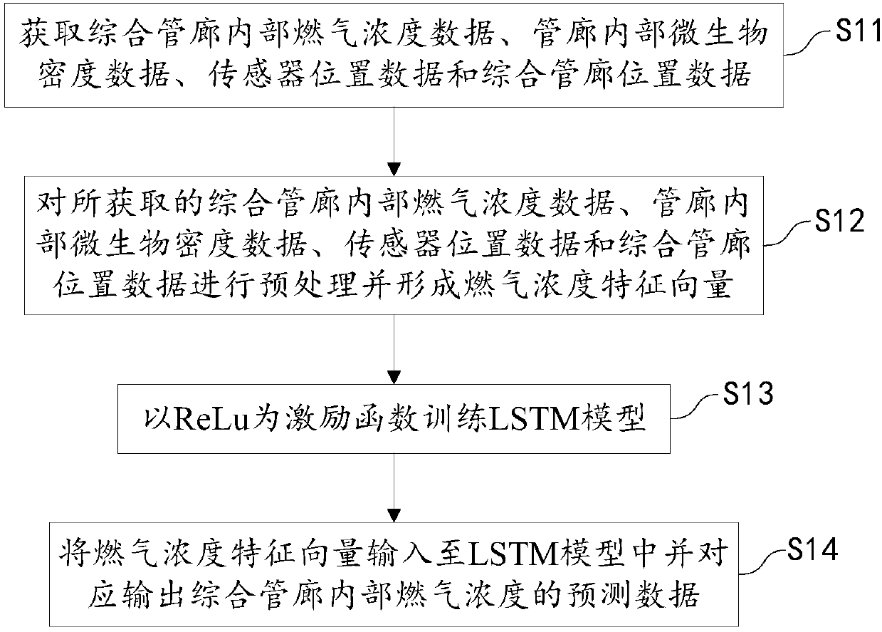
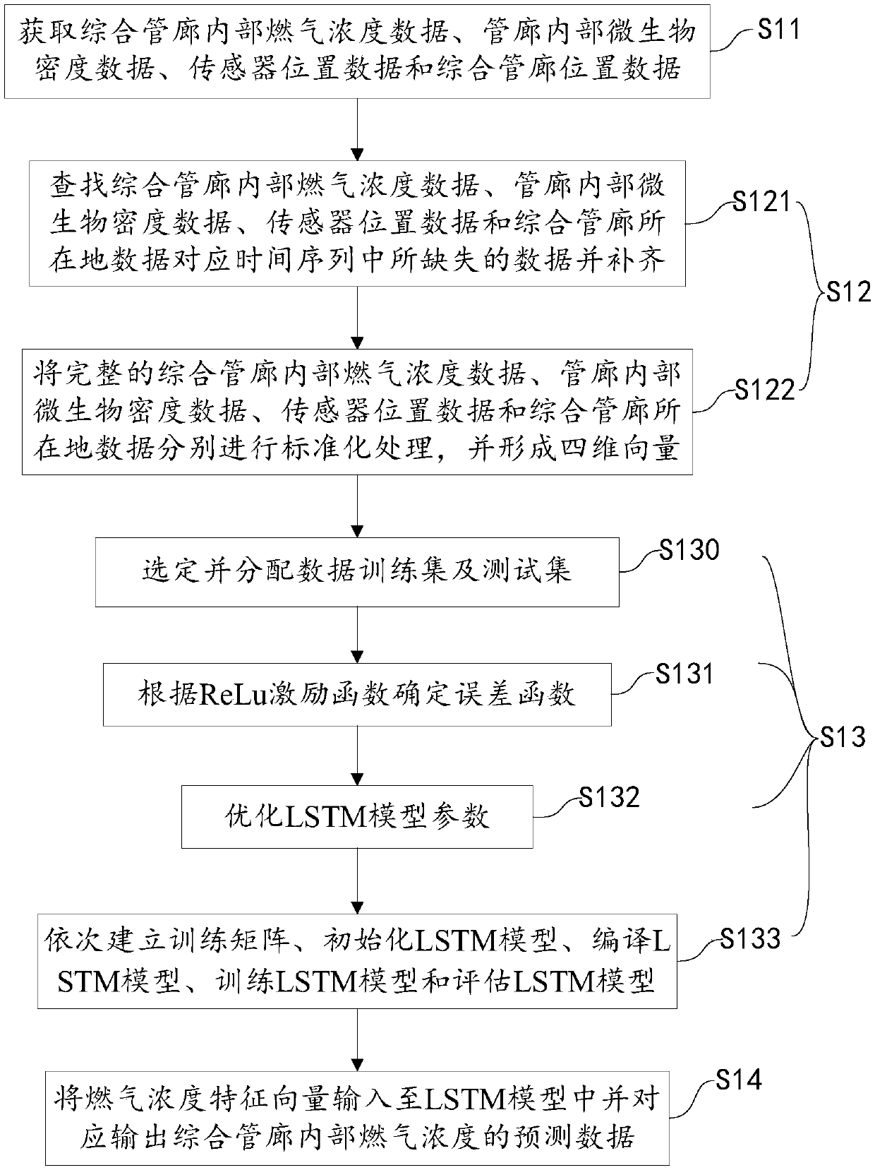
[0058] The embodiment of the present invention provides an LSTM prediction method for the internal gas concentration of the integrated pipe gallery, such as figure 1 As shown, the method includes:

[0059] S11. Obtain the gas concentration data inside the utility tunnel, the microbial density data inside the utility tunnel, the sensor locati...


PUM


Abstract

The invention provides a prediction method and system of internal combustion gas concentration LSTM of a comprehensive pipe rack. The prediction method of internal combustion gas concentration LSTM ofa comprehensive pipe rack includes the steps: acquiring the internal combustion gas concentration data of the comprehensive pipe rack, the internal microbe density data of the pipe rack, the sensor position data and the positional data of the comprehensive pipe rack; preprocessing the acquired internal combustion gas concentration data of the comprehensive pipe rack, the internal microbe densitydata of the pipe rack, the sensor position data and the positional data of the comprehensive pipe rack, and forming combustion gas concentration characteristic vectors; taking ReLu as an excitation function to train an LSTM model; and inputting the combustion gas concentration characteristic vectors into the LSTM model, and correspondingly outputting the predicted data of the internal combustion gas concentration of the comprehensive pipe rack. The prediction method and system of internal combustion gas concentration LSTM of a comprehensive pipe rack can construct a model by means of a recurrent neural network with a long short term memory, and is adapted to dynamic characteristics of the internal combustion gas concentration data of the comprehensive pipe rack so as to realize long-term accurate prediction of the internal combustion gas concentration data of the comprehensive pipe rack in advance. The prediction method and system of internal combustion gas concentration LSTM of a comprehensive pipe rack has the advantages of high universality, low cost and wide applicability.

Description

technical field [0001] The invention relates to the technical field of comprehensive utility tunnels, in particular to an LSTM prediction method and system for gas concentration inside a comprehensive utility tunnel. Background technique [0002] Urban underground comprehensive pipe gallery, also known as "common ditch", is a structure laid under the ground. It can accommodate various public pipelines such as telecommunications, electricity, water supply, and heat, and has complete drainage, lighting, communication, monitoring, etc. facility. The underground comprehensive pipe corridor is a municipal infrastructure created to ensure the full play of road functions, effectively utilize urban underground space, improve the urban environment, enhance the city's ability to resist earthquakes and disasters, and ensure the safe operation of the city. Up to now, more than 1,000 kilometers of underground comprehensive pipe corridors have been built across the country; more than 5,0...

Claims


Application Information

Patent Timeline
Patent Type & Authority Applications(China)
IPC IPC(8): G06Q10/04G06Q10/06G06N99/00
CPCG06N20/00G06Q10/04G06Q10/0635
Inventor 邱实陈雍君薛博宁楠
Owner 国通广达(北京)技术有限公司
Why Eureka
Try Eureka