
Electronic communication processing equipment

A processing equipment and communication technology, applied in the field of communication products, can solve the problems of external environmental pollution, hidden dangers to the safety of staff, etc., and achieve the effect of convenient operation and simple structure

Inactive Publication Date: 2018-08-21
张双锥
View PDF5 Cites 1 Cited by
  • Summary
  • Abstract
  • Description
  • Claims
  • Application Information

AI Technical Summary

Problems solved by technology

[0002] At present, with the continuous development of electronic communication technology, more and more electronic communication products are used. When producing and processing electronic communication products, it is necessary to drill holes in the shells of electronic communication products. The drill bit of the current drilling machine is exposed During production and processing, it is easy to cause pollution to the external environment, and it is easy to cause safety hazards to the staff. Therefore, there is an urgent need for a safe, efficient and high-quality electronic communication production equipment

Method used


Image

  • Electronic communication processing equipment
  • Electronic communication processing equipment
  • Electronic communication processing equipment

Examples


Embodiment Construction

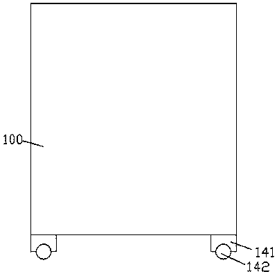
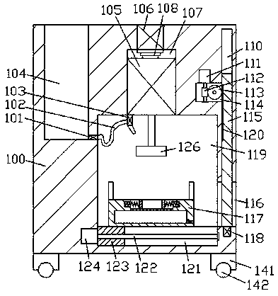
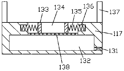
[0013] Combine below Figure 1-3 The present invention will be described in detail.

[0014] refer to Figure 1-3 , an electronic communication processing device according to an embodiment of the present invention, comprising a processing main body 100, a foot 141 is fixed around the bottom end surface of the processing main body 100, and a roller 142 is installed in rotation on the bottom end surface of the foot 141, the A cavity 119 is provided in the inner wall of the processing body 100, and a tightening seat 117 is mounted on the bottom end wall of the cavity 119 for sliding fit. 134 The inner walls of the left and right sides are symmetrically provided with recessed cavities 136, and the elastic parts 135 are fixed in the recessed cavities 136, and the elastic parts 135 on the left and right sides are fixed in the fastening cavity 134. Connected ejector plate 133, a storage cavity 132 is provided in the tightening seat 117 at the bottom of the tightening cavity 134, a ...


PUM


Abstract

The invention discloses electronic communication processing equipment. The electronic communication processing equipment comprises a processing main body, wherein supporting legs are fixedly arrangedon the periphery of the end surface of the bottom of the processing main body; a roller is mounted in the bottom end surface of each supporting leg in a running fit manner; a cavity is formed in the inner wall body of the processing main body; an impaction seat is mounted on the bottom end wall of the cavity in a sliding fit manner; an impaction cavity is formed in the top end surface of the impaction seat; recessed cavities are symmetrically formed in the inner walls of the left side and the right side of the impaction cavity; a spring piece is fixedly arranged in each recessed cavity; a pushing plate which is fixedly connected with the spring pieces on the left side and the right side is mounted in the impaction cavity in a sliding fit manner; a storage cavity is formed in the impactionseat and positioned at the bottom end of the impaction cavity; a screen is arranged between the storage cavity and the impaction cavity; an opening and closing valve which penetrates through the rightend surface of the impaction seat is arranged at the bottom end of the right side of the storage cavity; a slot which communicates with the cavity is formed in the right end surface of the processingmain body; and a first sliding cavity is formed in the inner bottom wall of the cavity.

Description

technical field [0001] The invention relates to the technical field of communication products, in particular to electronic communication processing equipment. Background technique [0002] At present, with the continuous development of electronic communication technology, more and more electronic communication products are used. When producing and processing electronic communication products, it is necessary to drill holes in the shells of electronic communication products. The drill bit of the current drilling machine is exposed During production and processing, it is easy to cause pollution to the external environment, and it is easy to cause safety hazards to the staff. Therefore, there is an urgent need for a safe, efficient and high-quality electronic communication production equipment. Contents of the invention [0003] The object of the present invention is to provide an electronic communication processing device for overcoming the above-mentioned defects in the pri...

Claims


Application Information

Patent Timeline
Patent Type & Authority Applications(China)
IPC IPC(8): B23B41/00B23B47/26B23B47/22B23Q11/00B23Q1/25B23Q3/06
CPCB23B41/00B23B47/26B23Q1/25B23Q3/062B23Q5/26B23Q11/00
Inventor 张双锥
Owner 张双锥
Learn More