Aeration device with stirring rods with gas outgoing holes

A technology of aeration device and stirring rod, which is applied in water aeration, biological treatment device, reflux water treatment, etc. It can solve the problems of poor stirring effect in aeration chamber, chaotic water flow, insufficient aeration of sewage, etc., and achieve aeration fuller effect

Inactive Publication Date: 2018-08-21
章慧
View PDF0 Cites 5 Cited by
  • Summary
  • Abstract
  • Description
  • Claims
  • Application Information

AI Technical Summary

Problems solved by technology

[0003] The aeration tank is a device for biochemical treatment of sewage. After the sewage enters the aeration tank, it reacts organically with the active mud in the tank, and the harmful substances are decomposed into harmless substances, which are discharged after the water is clarified. During the treatment process, in order to maintain The life activities of microorganisms must ensure that there is a certain amount of dissolved oxygen in the water. The so-called aeration is to continuously inject air into the water, or use mechanical stirring to dissolve the oxygen in the air into the water; the current aeration methods mainly include blasting There are two kinds of aeration and mechanical aeration. Blast aeration is to use the aerator to inject air into the aeration head and diffuse it into the water to form bubbles, and dissolve oxygen in the water at the gas-liquid interface; the distribution of the jet holes of the ordinary aeration device The area is single, the stirring effect in the aeration chamber is poor, and the water flow is chaotic, which makes the sewage aeration insufficient, resulting in incomplete sewage treatment

Method used


Image

  • Aeration device with stirring rods with gas outgoing holes
  • Aeration device with stirring rods with gas outgoing holes
  • Aeration device with stirring rods with gas outgoing holes

Examples


Embodiment Construction

[0019] In order to enable those skilled in the art to better understand the solutions of the present invention, the technical solutions in the embodiments of the present invention will be clearly and completely described below in conjunction with the drawings in the embodiments of the present invention.

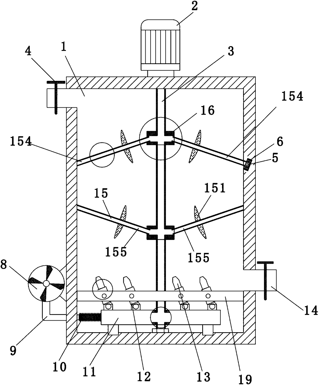
[0020] Such as Figure 1 to Figure 5 As shown, an aeration device with a stirring rod with an air outlet, including an aeration chamber 1, a motor 2 arranged on the top of the aeration chamber 1, a stirring module arranged inside the aeration chamber 1, and an aeration chamber 1 The aeration module at the bottom; the aeration module includes an air pump 8 arranged outside the aeration chamber 1 and an aeration pan 11 arranged at the bottom of the aeration chamber 1, and a telescopic tube is arranged between the aeration pan 11 and the air pump 8 10 connection, the aeration chamber 1 is isolated from the aeration module by a bottom plate 19, and the bottom plate 19 is provided...


PUM


Abstract

The invention discloses an aeration device with stirring rods with gas outgoing holes. The aeration device comprises an aeration cavity, a motor arranged at the top of the aeration cavity, a stirringmodule arranged inside the aeration cavity and an aeration module arranged on the lower portion of the aeration cavity, the stirring module comprises a rotating shaft fixedly connected with the outputend of the motor and a stirring rod group rotatably connected with the rotating shaft, and the rotating shaft and the stirring rod group are hollow cylinders; the gas outgoing holes and propellers are arranged on the stirring rod group, and the stirring rod group is arranged in a manner of inclining relative to the rotating shaft. Gas can be fed into after the rotating shaft and the stirring rodgroup are connected with the aeration module, and the gas is ejected from the gas outgoing holes formed in the stirring rod group to realize multidirectional aeration effect, so that aeration is moresufficient; the propellers are arranged on the stirring rod group to enable sewage to move along a fixed direction to form circulating water flow inside, in this way, circulating sewage flow is enabled to pass the gas outgoing holes so as to realize sufficient aeration effect.

Description

technical field [0001] The invention belongs to the field of environmental protection, and in particular relates to an aeration device with an air outlet on a stirring rod. Background technique [0002] The problem of water pollution is an environmental problem throughout the world. According to the methods used in sewage treatment, it can be divided into four types: physical method, chemical method, physical chemical method and biological method. Biological method is a method of using the metabolism of microorganisms in wastewater to decompose degradable organic matter in sewage. Because of its large processing capacity, low investment, and economical reliability, it has become the most common water treatment method in the world today. [0003] The aeration tank is a device for biochemical treatment of sewage. After the sewage enters the aeration tank, it reacts organically with the active mud in the tank, and the harmful substances are decomposed into harmless substances, ...

Claims


Application Information

Patent Timeline
Patent Type & Authority Applications(China)
IPC IPC(8): C02F7/00C02F3/20
CPCC02F3/206C02F7/00C02F2201/002C02F2203/006C02F2301/04Y02W10/10
Inventor 章慧
Owner 章慧
Why Eureka
Try Eureka