Mold and method for manufacturing mold

A manufacturing method and mold technology, which are applied in the field of injection molding molds and injection molding mold manufacturing fields, can solve the problems of difficult to form water pipe paths, difficult to reliable temperature control, easy damage to O-rings, etc. The effect of shortened molding cycle and reliable temperature control

Active Publication Date: 2018-08-21
PANASONIC INTELLECTUAL PROPERTY MANAGEMENT CO LTD
View PDF7 Cites 0 Cited by
  • Summary
  • Abstract
  • Description
  • Claims
  • Application Information

AI Technical Summary

Problems solved by technology

However, it is not easy to use special tools such as gun drills to form water pipe paths on the side of the mold on the fixed side of the mold
In addition, it is not easy to form a water pipe path when drilling holes in the mold base
In addition, if a high-temperature refrigerant is used as the coolant, the O-ring is easily damaged
In addition, maintenance within the water pipe path is difficult in cases where the water pipe path is formed using special tools such as a gun drill
In addition, since the inlet and outlet of the coolant channel are not directly connected to the cooling pipe, it is not easy to reliably control the temperature.

Method used


Image

  • Mold and method for manufacturing mold
  • Mold and method for manufacturing mold
  • Mold and method for manufacturing mold

Examples


Embodiment 1

[0057] A molded product was obtained under the following conditions.

[0058] Resin material: PPWW567w3952

[0059] Mold: (size) 300mm×500mm×345mm / (mass) 403kg

[0060] Molding machine: Nissei ES2000

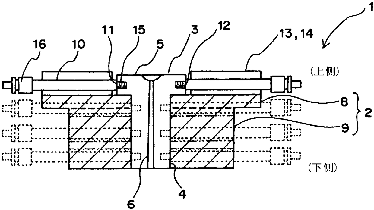
[0061] Such as Figure 8A and Figure 8B As shown, the mold 1 for injection molding according to one embodiment of the present invention can shorten the cooling time of the molten resin from 13 s to 8 s compared with the conventional mass production mold, and as a result, the overall molding cycle can be shortened by 25.7%. (35s→26s).

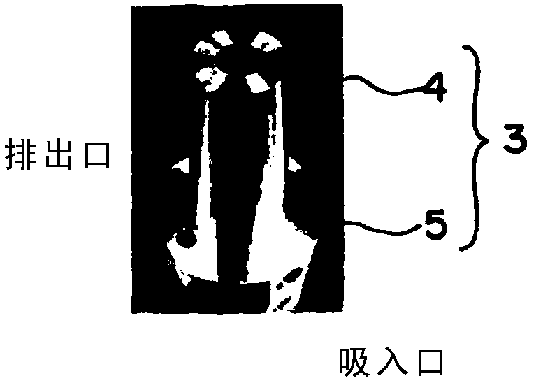
[0062] In the case of using the mold 1 for injection molding according to one embodiment of the present invention, as Figure 8C As shown in the photo, the sprue runner part is in a good state because the cooling temperature of the molten resin can be properly controlled to sufficiently cool the molten resin. On the other hand, in the case of using conventional mass production molds, such as Figure 8D As shown, the cooling temperature of ...

Embodiment 2

[0064] Such as Figure 9A and Figure 9B As shown, the mold 1 for injection molding according to one embodiment of the present invention can shorten the cooling time of the molten resin from 39s to 25s compared with the conventional mass production mold, and as a result, the overall molding cycle can be shortened by 30.8%. (65s→45s).

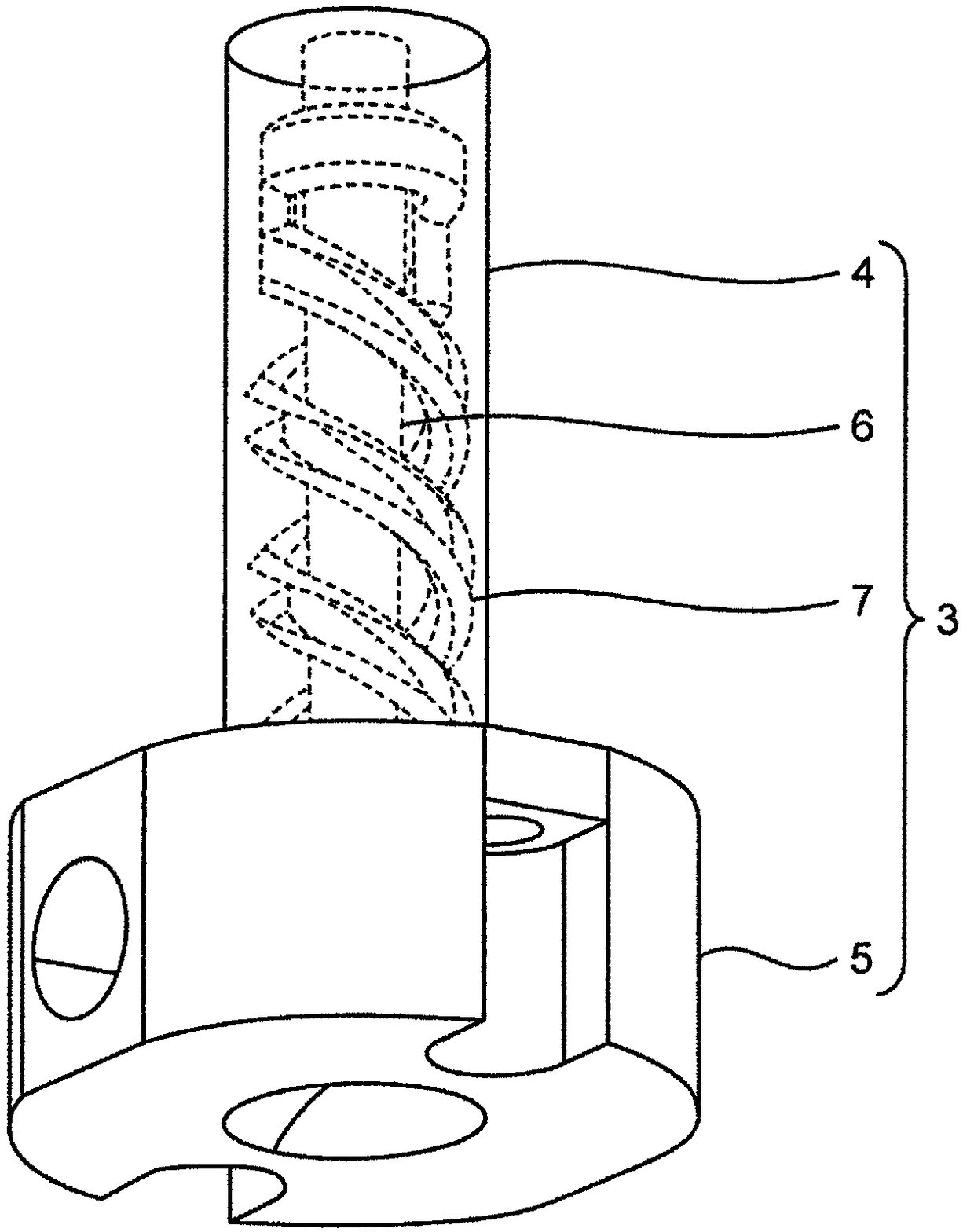
[0065] In the case of using the injection mold 1 according to the embodiment of the present invention, since the cooling temperature of the molten resin can be appropriately controlled to sufficiently cool the molten resin, the sprue does not elongate. In addition, the temperature analysis of the sprue bushing 3 between the cooling steps was carried out, such as Figure 9CAs shown, it can be seen that the temperature near the injection port of the sprue bushing is sufficiently cooled compared with other parts of the sprue bushing. On the other hand, in the case of using a conventional mass-production mold, the cooling temperature of the molte...


PUM


Abstract

The present invention provides a mold comprising the following: a movable-side mold; a fixed-side mold; and a sprue bush disposed inside the fixed-side mold and provided with a cooling liquid flow path. The mold is characterized in that both the inlet portion and the outlet portion of the cooling liquid flow path are directly connected to a cooling tube disposed along a space region formed in thefixed-side mold, and in that the space region has a form in which at least one surface of the fixed-side mold has an opening.

Description

technical field [0001] The invention relates to a mold and a method for manufacturing the mold. Specifically, the present invention relates to a mold for injection molding and a method for manufacturing the mold for injection molding. Background technique [0002] As one of the technologies supporting Japan's "manufacturing" industry, there is molding technology using molds. Examples of such molding techniques include press molding, injection molding, extrusion molding, and injection molding. Among these molding methods, the injection molding method is mainly a method of obtaining a molded product by injecting heated and molten resin into a mold, cooling and solidifying it, and is suitable for mass production of molded products with complex shapes. The steps of the injection molding method are generally composed of a mold clamping step, an injection step, a cooling step, and a mold opening step. By repeating these steps, molded articles can be produced continuously. [0...

Claims


Application Information

Patent Timeline
Patent Type & Authority Applications(China)
IPC IPC(8): B29C45/73B29C45/27
CPCB29C45/26B29C45/27B29C45/2737B29C45/7312B29C2045/2753
Inventor 阿部谕田中健一内野野良幸松本武武南正孝
Owner PANASONIC INTELLECTUAL PROPERTY MANAGEMENT CO LTD
Why Eureka
Try Eureka