Steel plate drilling machine with water circulation function

A drilling machine and water circulation technology, applied in the direction of boring/drilling, drilling/drilling equipment, manufacturing tools, etc., can solve the problems of increasing the work intensity of employees, unable to recover water flow, waste of water resources, etc., to save resources , The effect of reducing work intensity and large washing range

Inactive Publication Date: 2018-08-24
芜湖良匠机械制造有限公司
0 Cites 9 Cited by

AI-Extracted Technical Summary

Problems solved by technology

[0002] Drilling the steel plate is a very common process in the steel plate processing process. When drilling the steel plate, it is necessary to cool the drilled hole with water in order to reduce the wear of the drill bit and the deformation of the drilled hole. At present, most of them are manually drilled. The water in the plastic bottle is squeezed out to the drill hol...

Method used

Below by the description of embodiment, the specific embodiment of the present invention is as the shape of each member involved, structure, mutual position and connection relationship between each part, the effect of each part and working principle, manufacturing process and The operation and use methods, etc. are further described in detail to help those skilled in the art have a more complete, accurate and in-depth understanding of the inventive concepts and technical solutions of the present invention.
In order to improve the flushing scope of water outlet device, water outlet device comprises water pipe 9, and water pipe 9 passes top beam 3 and is connected together with the bottom of water tank 8, and water pipe is provided with valve 10, and flexible pipe 13 is installed at the bottom of water pipe 9, The lower end of the hose 13 is sleeved with a sleeve 14 , the bottom of the sleeve 14 is fixedly connected with a short rod 15 , and the short rod 15 is rotatably connected with a conne...

Abstract

The invention discloses a steel plate drilling machine with a water circulation function, and relates to the technical field of steel plate machining equipment. The steel plate drilling machine comprises a box body. A stand column is arranged in the middle of the interior of the box body. A workbench is arranged at the top of the stand column. Baffles are arranged on the upper edge, the lower edgeand the right edge of the top of the workbench. The top of the box body is fixedly connected with a top beam through supports. A drilling device used for drilling a steel plate is connected to the top beam. A waste scrap filtering mechanism is further arranged in the box body. A water circulation device is arranged between the top beam and the box body and used for flushing and cooling the steelplate when the steel plate is drilled. Through the design of the waste scrap filtering mechanism, waste scraps can be conveniently and effectively recovered, and resources are saved; through the design of the water circulation device, water can be automatically sprayed to a drilled hole, so that the work intensity of workers is relieved, and meanwhile, water resources are saved; and through the design of a water outlet device, water can flush the steel plate in a wider range, and thus, the practicability of the steel plate drilling machine is improved.

Application Domain

Maintainance and safety accessoriesBoring/drilling machines

Technology Topic

Water circulationSteel plates +7

Image

  • Steel plate drilling machine with water circulation function

Examples

  • Experimental program(1)

Example Embodiment

[0015] Through the description of the embodiments below, the specific implementation of the present invention includes the shape, structure, mutual position and connection relationship between the various parts, the function and working principle of each part, the manufacturing process and the operation and use method of the various components involved. etc., to make further detailed descriptions to help those skilled in the art have a more complete, accurate and in-depth understanding of the inventive concepts and technical solutions of the present invention.
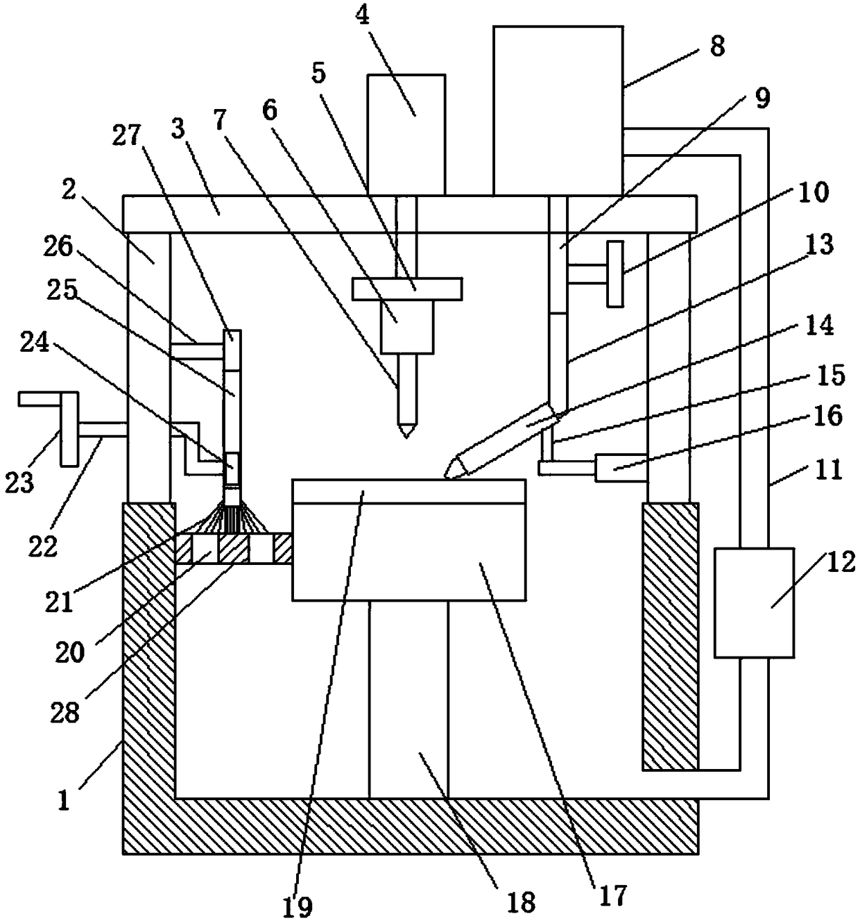
[0016] like figure 1 As shown, a steel plate drilling machine with water circulation function includes a box body 1, a column 18 is provided at the inner middle part of the box body 1, and a workbench 17 is provided at the top of the column 18, and the workbench 17 The upper, lower and right edges of the top are provided with baffles 19, and the top of the box body 1 is fixedly connected with a top beam 3 through a bracket 2, and the top beam 3 is connected with a drilling device for drilling of steel plates. The inside of the box 1 is also provided with a waste filter mechanism, and a water circulation device is also provided between the top beam 3 and the box 1 for washing the steel plate and cooling it when the steel plate is drilled.
[0017] In this embodiment, the drilling device includes a driving device 4, a mounting plate 5, a motor 6 and a drill rod 7, the driving device 4 is installed on the top of the top beam 3, the mounting plate 5 and the driving device 4 are fixedly connected together, The motor 6 is fixedly connected to the bottom of the mounting plate 5, and the drill rod 7 is connected with the rotating shaft of the motor 6.
[0018] When the drilling device is working, the driving device 4 is used to complete the lifting and lowering of the drilling rod 7, and the motor 6 works to drive the drilling rod 7 to rotate to carry out the drilling operation.
[0019] In this embodiment, the waste filter mechanism includes a filter plate 28, a rotating rod 22, a slide block 24, a swing rod 27, a connector 26, a handle 23 and a brush 21, and the side wall of the filter plate 28 is fixedly connected to the On the inner wall of the box body 1 and the side of the workbench 17, and the filter plate 28 is positioned on the side of the top of the workbench 17 without the baffle plate 19, the filter plate 28 is provided with a through hole 20 for water supply, and the rotating rod 22 rotates with the support 2 Connect together, turn bar 22 becomes Z shape, and one end of turn bar 22 is fixedly connected together with slide block 24, and the other end is fixedly connected together with handle 23, and swing bar 27 is provided with chute 25, and chute 25 and slide The blocks 24 are slidably connected together, one end of the connector one 26 is fixedly connected to the surface of the support 2, and the other end is rotationally connected with the upper end of the swing bar 27. The tops touch.
[0020] When carrying out the drilling operation, the water circulation device flushes the steel plate, because the design of the baffle plate 19 makes the waste chips on the steel plate rush to the filter plate 28, and the water flows to the bottom of the casing 1 through the through hole 20 on the filter plate 28, and the waste Chips stay on the top of the filter plate 28 so that the waste chips are reclaimed, so that the separation of water and waste chips is realized. When the waste chips on the filter plate 28 accumulate to a certain extent and affect the passage of water, turn the handle 23 now The slider 24 is rotated by the turning rod 22, and the slider 24 slides in the chute 25 at the same time, and the slider 25 drives the swing lever 27 to swing around the connector one 26, so that the back and forth swing of the hair brush 21 will remove the dust on the filter plate 28 The waste chips are swept towards both sides of the filter plate 28, which ensures that the water flow can pass through the filter plate 28 normally.
[0021] In this embodiment, the water circulation device includes a water tank 8, a water outlet device, a communication pipe 11 and a water pump 12. One end of the communication pipe 11 is connected to the water tank 8, and the other end is connected to the lower end of the box body 1. The water tank 8 is fixedly connected to the top The top of the beam 3, the water outlet device passes through the top beam 3 and is connected to the bottom of the water tank 1, and the water pump 12 is connected in series on the connecting pipe 11, and the water outlet device is used for leading the water in the water tank to the borehole.
[0022] The water in the water tank 8 flows from the water outlet device to the drill hole of the steel plate to cool the steel plate and the drill pipe. At the same time, the steel plate is washed to remove the waste chips on the steel plate. Transport back in the water tank 8, realize the recycling of water like this, save water resources.
[0023] In order to improve the flushing range of the water outlet device, the water outlet device includes a water pipe 9, the water pipe 9 passes through the top beam 3 and is connected to the bottom of the water tank 8, the water pipe is provided with a valve 10, and the bottom of the water pipe 9 is equipped with a hose 13, the hose 13 The lower end of the sleeve 14 is sleeved, and the bottom of the sleeve 14 is fixedly connected with a short rod 15, and the short rod 15 is rotatably connected with a connector two 16, and one end of the connector two 16 is fixedly connected to the surface of the support 2. In this way, the water outlet direction can be changed by rotating the sleeve 14, which improves the practicability of the water outlet device.
[0024] In this embodiment, the connecting part 2 16 is a telescopic part, and the short rod 15 is rotatably connected with the telescoping end of the telescopic part. In this way, the water outlet can move in the horizontal direction, further improving the flushing range of the water outlet device.
[0025] In this embodiment, the filter plate 28 is made of plastic.
[0026] In this embodiment, the driving device 4 is hydraulic steel.
[0027] The present invention has been exemplarily described above in conjunction with the embodiments, and it is obvious that the specific implementation of the present invention is not limited by the above-mentioned manner, as long as various insubstantial improvements are adopted in the method concept and technical scheme of the present invention, or without improvement Directly applying the conception and technical solutions of the present invention to other occasions falls within the protection scope of the present invention. The protection scope of the present invention should be determined by the protection scope defined in the claims.

PUM

no PUM

Description & Claims & Application Information

We can also present the details of the Description, Claims and Application information to help users get a comprehensive understanding of the technical details of the patent, such as background art, summary of invention, brief description of drawings, description of embodiments, and other original content. On the other hand, users can also determine the specific scope of protection of the technology through the list of claims; as well as understand the changes in the life cycle of the technology with the presentation of the patent timeline. Login to view more.

Similar technology patents

Rail transportation system powered by solar energy

InactiveCN101774355Asave resourcesSmall installation space
Owner:HEFEI BOPU HIGH TECH

Method, system and single board for realizing net port switching

InactiveCN101052053AReduce the number of signalssave resources
Owner:NEW H3C TECH CO LTD

Classification and recommendation of technical efficacy words

  • save resources
  • Reduce work intensity

Software test apparatus and test method

Owner:KINGDEE SOFTWARE(CHINA) CO LTD

Granular pesticide fertilizer, and preparation method and application thereof

InactiveCN102775241AReduce stress on the farm environmentsave resources
Owner:SHENZHEN NOPOSION AGROCHEM

Distributed indesx file searching method, searching system and searching server

ActiveCN101071442Asave resourcesImprove coupling
Owner:SHENZHEN SHI JI GUANG SU INFORMATION TECH

Composite admixture for cement or high-performance concrete and preparation method thereof

InactiveCN102180612Asave resourcesgood social benefits
Owner:葫芦岛市辽西混凝土外加剂有限公司

Powerless voltage automatic control system for area power grid

InactiveCN101106274AReduce network loss and operating costsReduce work intensity
Owner:SHANGHAI JIAO TONG UNIV

Quick automatic artillery aiming device

InactiveCN101881580AReduce work intensityImprove emission efficiency
Owner:ZHEJIANG UNIV OF TECH

Concrete laminating curing machine

Owner:盐城欣昌新型建材有限公司
Why Eureka
Try Eureka