

Full-automatic ultrasonic flexible welding device
A welding device and ultrasonic technology, applied in auxiliary devices, welding equipment, welding equipment and other directions, can solve the problems of slow production speed, high labor intensity, affecting the quality of workpieces, etc., to improve processing efficiency, improve welding efficiency, and reduce labor consumption. Effect
- Summary
- Abstract
- Description
- Claims
- Application Information
AI Technical Summary
Problems solved by technology
Method used
Image

Examples
Embodiment 1
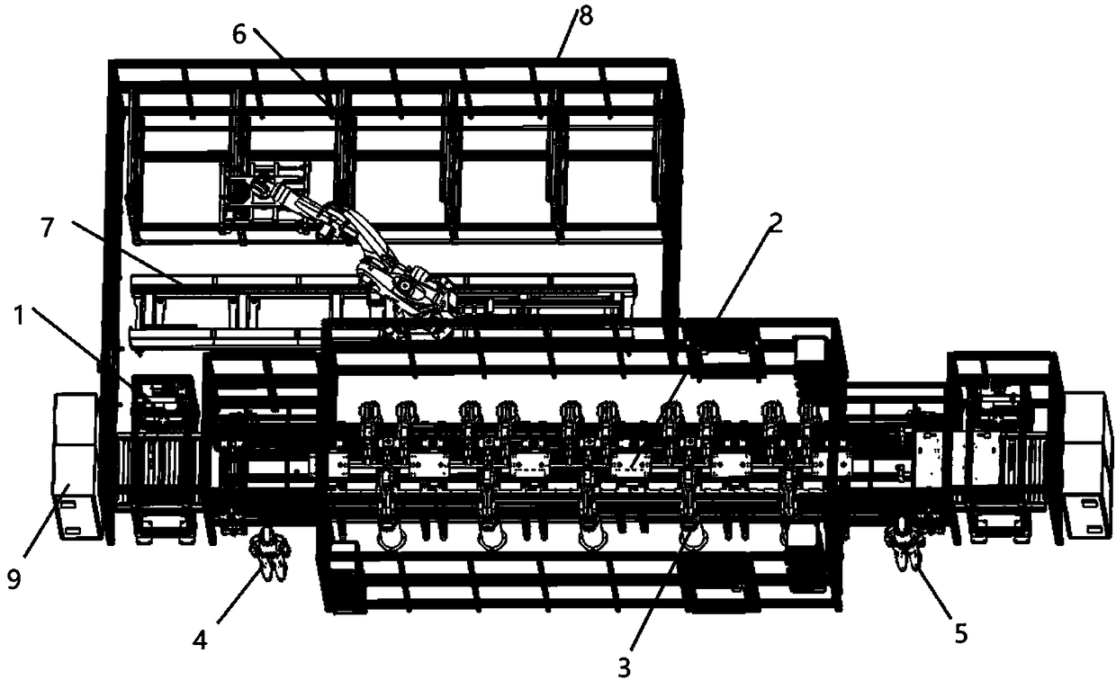
[0028] Such as figure 1 As shown, the embodiment of the present application provides a fully automatic ultrasonic flexible welding device, including a welding production line, a three-dimensional storage warehouse 6, a robot handling mechanism 7, and a safety fence 8. The robot handling mechanism 7 is located between the three-dimensional storage warehouse 6 and the welding production line. Between, the welding production line, the three-dimensional storage warehouse 6, and the robot handling mechanism 7 are located in the safety fence 8; the welding production line is used to weld the parts to be welded; the robot handling mechanism 7 is used to replace the pallet; the safety fence is used To ensure the safety of operation; the three-dimensional storage warehouse 6 is used to store pallets.
Embodiment 2
[0030] In the embodiment of the present invention, the welding production line includes two elevators 1 with the same structure, a conveying mechanism, and a tray 10 for placing parts to be welded. The elevators 1 are located at both ends of the conveying mechanism. Driven by the hoist and conveying mechanism.
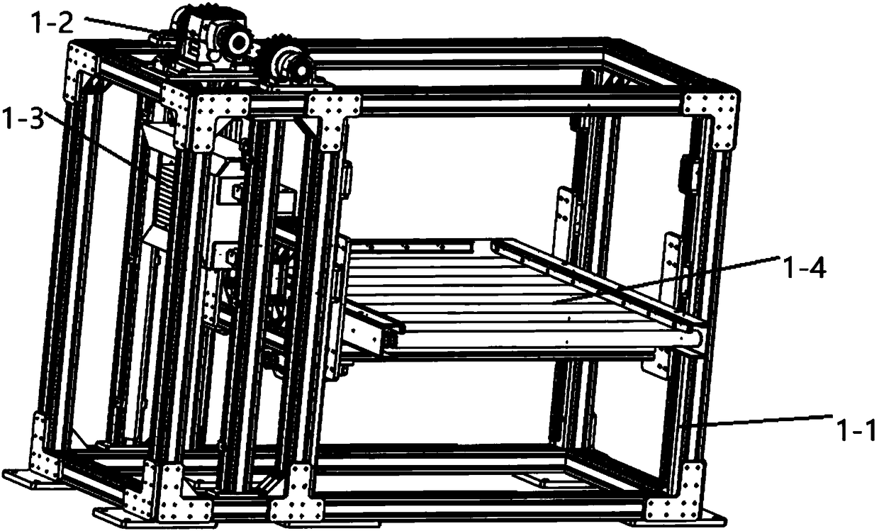
[0031] Among them, such as Figure 2-5 As shown, the hoist 1 includes a hoist frame 1-1, a hoist power mechanism 1-2, a counterweight mechanism 1-3, and a tray conveying mechanism 1-4, and the hoist power mechanism 1-2 is arranged on the hoist On the upper part of the machine frame 1-1, the counterweight mechanism 1-3 is arranged inside the left side of the hoist frame 1-1, and the pallet conveying mechanism 1-4 is arranged inside the right side of the hoist frame 1-1.
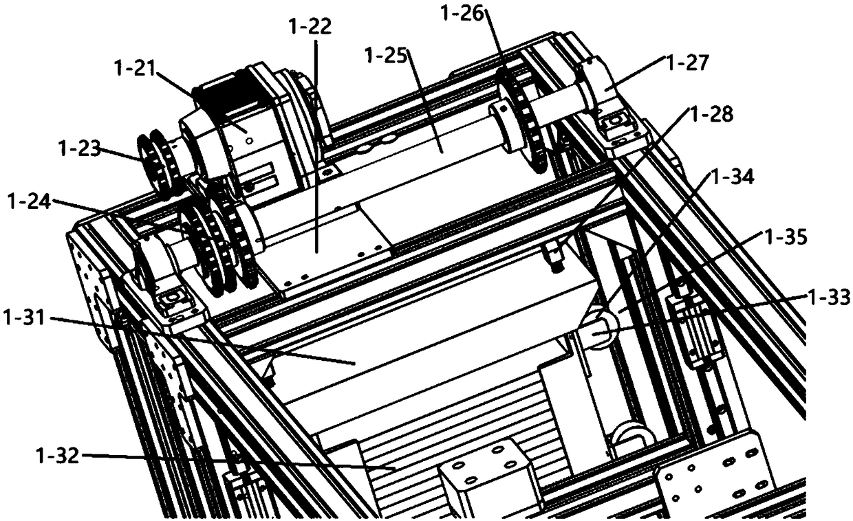
[0032] Wherein, the hoist power mechanism 1-2 includes a hoist motor 1-21 and a hoist shaft 1-25, and the hoist motor 1-21 is fixedly connected to the hoist frame 1-1 through a motor connection plate ...
Embodiment 3
[0049] In the embodiment of the present invention, such as Figure 10 As shown, the robot transport mechanism 7 includes a transport robot 7-1, a transport robot base 7-2, a ground rail 7-3, a robot drive rack 7-4, and a robot drive motor 7-5. The transport robot 7- 1 The robot base 7-2 is slidingly connected to the ground rail 7-3, the robot drive rack 7-4 is arranged laterally on the ground rail 7-3, and the robot drive motor 7-5 is installed on the transport robot 7- 1, the drive shaft of the robot drive motor 7-5 is equipped with a gear used in conjunction with the robot drive rack 7-4, and drives the robot drive rack 7-4 through relative movement with the robot drive rack 7-4. The transfer robot 7-1 moves on the ground rail 7-3.
PUM
| Property | Measurement | Unit |
|---|---|---|
| Size | aaaaa | aaaaa |
Abstract
Description
Claims
Application Information