
Laser milling machine for road

A milling machine and laser technology, which is applied in the field of road milling machines, can solve the problems of handrails stored in the machine, arm paralysis, motor vibration, etc., and achieve the effect of simple structure, avoiding paralysis, and improving work efficiency

Inactive Publication Date: 2018-08-24
JIANGSU KERUIXIN MACHINERY
View PDF0 Cites 0 Cited by
  • Summary
  • Abstract
  • Description
  • Claims
  • Application Information

AI Technical Summary

Problems solved by technology

[0002] Road milling machine is one of the main types of asphalt pavement maintenance construction machinery, one of the main equipment for asphalt concrete road maintenance construction, laser is a kind of light, like other natural light, it is produced by atomic transition, so laser has very Pure color, almost non-divergent directionality, extremely high luminous intensity and high coherence; the existing laser milling machines for roads have certain disadvantages when they are used. First, the motor will produce violent vibrations when working , so that the arms of the staff are paralyzed by vibration during work, which is not conducive to work. Secondly, the handrails of the existing road laser milling machines are fixed, which takes up a lot of space when not in use. At the same time, they cannot be used very well. Storing the handrails on the machine has a certain impact on the user. Therefore, we propose a laser milling machine for roads

Method used


Image

  • Laser milling machine for road
  • Laser milling machine for road
  • Laser milling machine for road

Examples


Embodiment Construction

[0017] In order to make the technical means, creative features, goals and effects achieved by the present invention easy to understand, the present invention will be further described below in conjunction with specific embodiments.

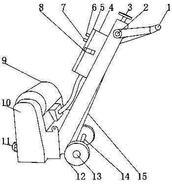
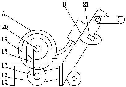
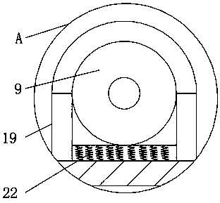
[0018] Such as Figure 1-4 As shown, a laser milling machine for roads includes a machine main body 15, a rubber walking wheel 12 is fixedly installed on the outer surface of the lower end of the machine main body 15 to prevent damage to the road surface, and a connecting shaft is movably installed on one side of the outer surface of the rubber walking wheel 12 14, and the other side outer surface of rubber walking wheel 12 is movably installed with locking bolt 13, is convenient to fix rubber walking wheel 12, and the front end outer surface of machine main body 15 is fixedly installed with depth adjusting handle 3, is convenient to adjust the position Cutting depth, the outer surface of one side of the main body 15 of the machine is movably equi...


PUM


Abstract

The invention discloses a laser milling machine for a road. The laser milling machine comprises a machine main body, wherein rubber walking wheels are fixedly mounted on the outer surface of the lowerend of the machine main body; a connecting shaft is moveably mounted on the outer surfaces of one sides of the rubber walking wheels; locking bolts are moveably mounted on the outer surfaces of the other sides of the rubber walking wheels; a depth adjusting handle is fixedly mounted on the outer surface of the front end of the machine main body; a handle rotating shaft is moveably mounted on theouter surface of one side of the machine main body; an anti-sliding handle is fixedly mounted on the outer surface of one side of the handle rotating shaft. The laser milling machine for the road is equipped with a damping mechanism, the handle rotating shaft and a handle fixing clamp, vibration of a motor can be reduced, operation can be facilitated, the working efficiency can be improved, the position of the handle can be conveniently adjusted, the space can be saved, the handle can be conveniently fixed on the machine main body, the handle is prevented from shaking back and forth in transportation, and relatively good application prospects can be achieved.

Description

technical field [0001] The invention relates to the technical field of road surface milling machines, in particular to a laser milling machine for roads. Background technique [0002] Road milling machine is one of the main types of asphalt pavement maintenance construction machinery, one of the main equipment for asphalt concrete road maintenance construction, laser is a kind of light, like other natural light, it is produced by atomic transition, so laser has very Pure color, almost non-divergent directionality, extremely high luminous intensity and high coherence; the existing laser milling machines for roads have certain disadvantages when they are used. First, the motor will produce violent vibrations when working , so that the arms of the staff are paralyzed by vibration during work, which is not conducive to work. Secondly, the handrails of the existing road laser milling machines are fixed, which takes up a lot of space when not in use. At the same time, they cannot ...

Claims


Application Information

Patent Timeline
Patent Type & Authority Applications(China)
IPC IPC(8): E01C23/088
CPCE01C23/088
Inventor 蔡敦军
Owner JIANGSU KERUIXIN MACHINERY
Learn More