Electric valve

A technology of electric valves and spools, applied in the direction of lift valves, valve devices, engine components, etc., can solve the problems of large occupied space, high economic expenditure, large size, etc., to achieve easy connection and use, reduce failure rate, and ensure sealing sexual effect

Pending Publication Date: 2018-08-24
诸暨市海王消防设备有限公司
View PDF0 Cites 2 Cited by
  • Summary
  • Abstract
  • Description
  • Claims
  • Application Information

AI Technical Summary

Problems solved by technology

[0002] There are two major problems in the use of traditional solenoid valves in the pipeline network. The first problem is the high cost. When large-scale branch pipeline networks are required, the economic expenditure is too high. The second problem is that they are large in size, especially for high-pressure pipeline networks. Solenoid valve, large size, takes up a lot of space

Method used


Image

  • Electric valve
  • Electric valve
  • Electric valve

Examples


Embodiment 1

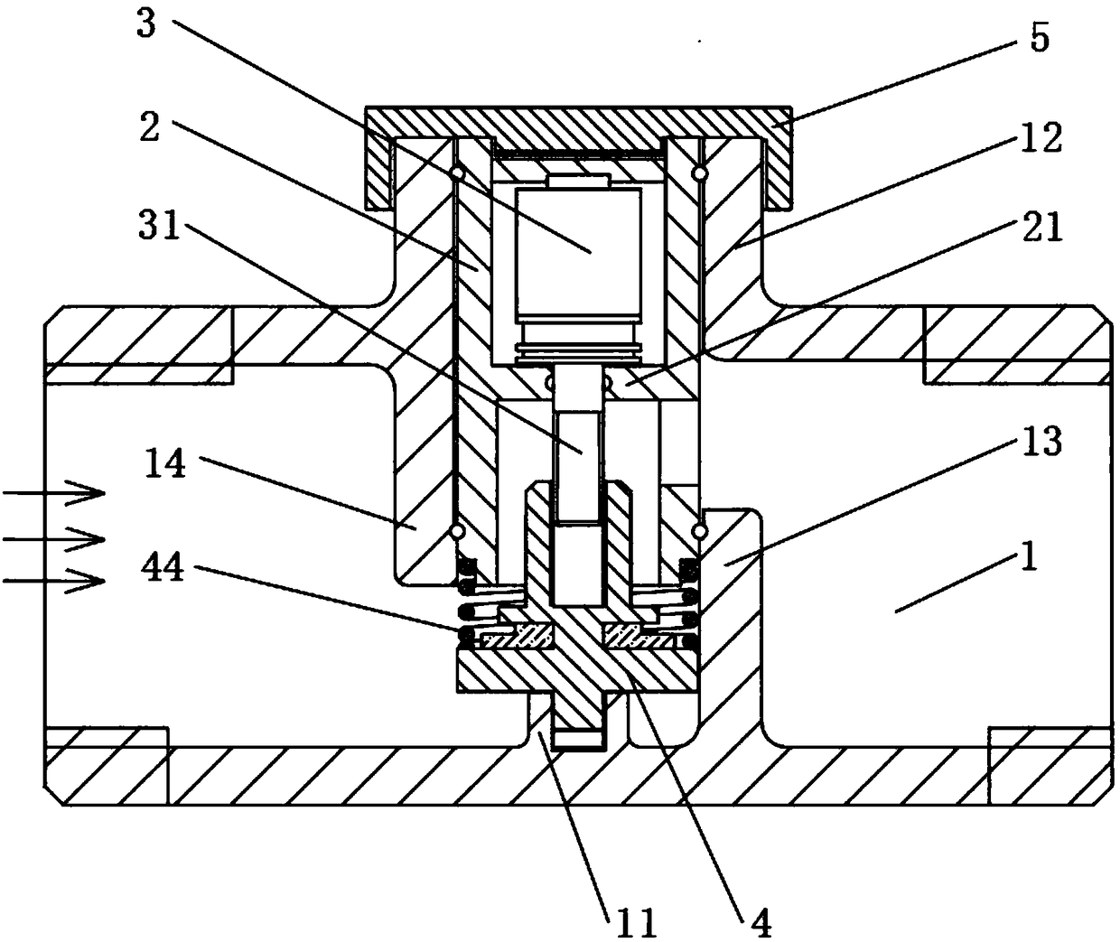
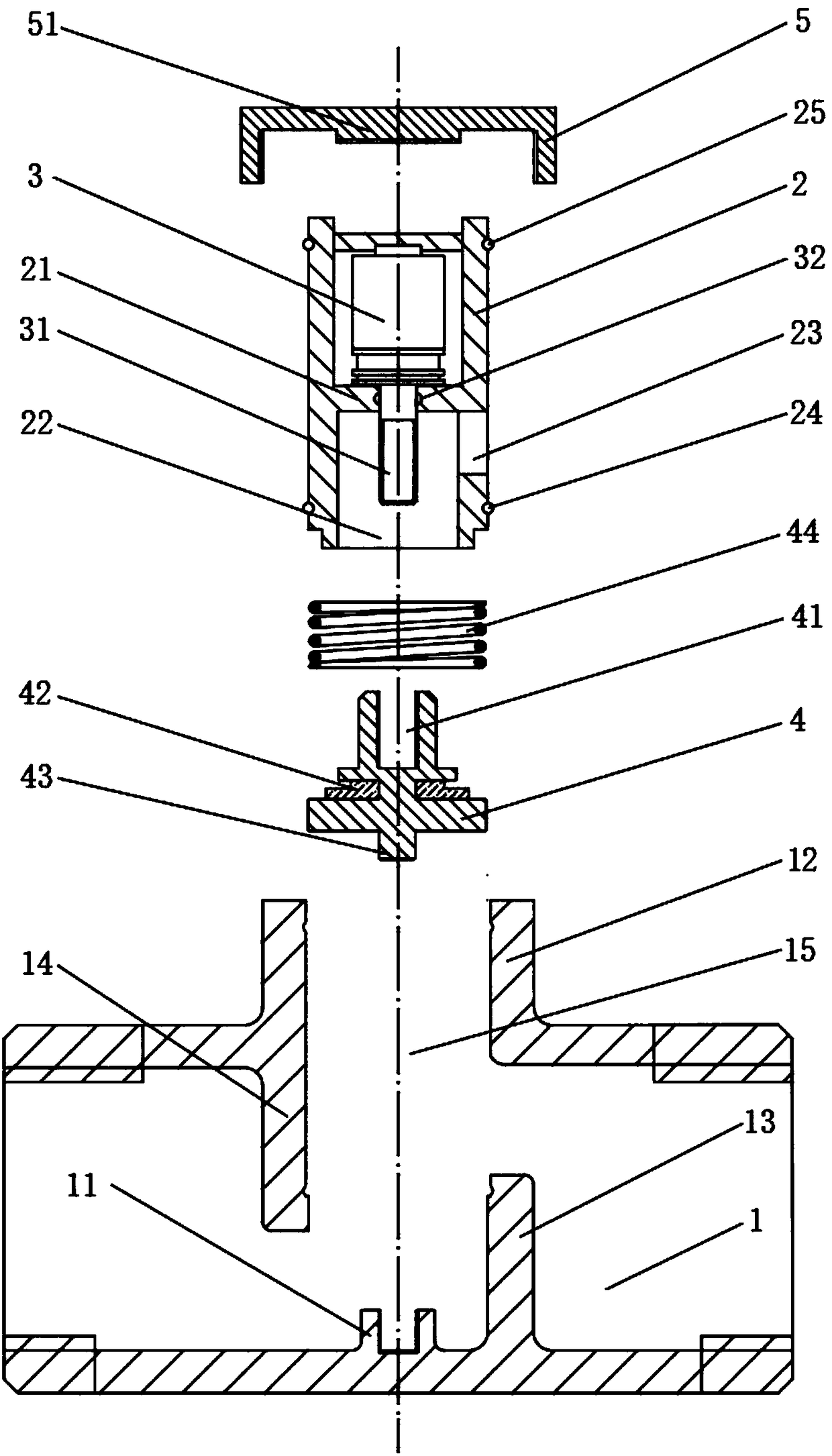
[0039] Embodiment one, according to figure 1 with figure 2 Shown:

[0040] An electric valve, characterized in that, comprising

[0041] Valve body 1, one side of the valve body 1 is provided with an extension part 12, the extension part 12 is connected with the valve body 1, and forms a valve core insertion cavity 15, the valve body 1 is opposite to the valve body The core insertion cavity 15 is connected with an upper baffle 14 and a lower baffle 13; the upper baffle 14 and the lower baffle 13 are respectively arranged on the upper left and lower right sides of the valve body 1 relative to the valve core insertion cavity 15 , the positive projection between the upper 14 and the lower 15 baffles overlaps, forming a Z-shaped flow channel with the valve body 1;

[0042] The spool 2 is located in the spool insertion cavity 15, the front end of the spool 2 is located in the middle of the Z-shaped flow channel, and a sealing ring 224 is arranged on the outside of the front end...

Embodiment 2

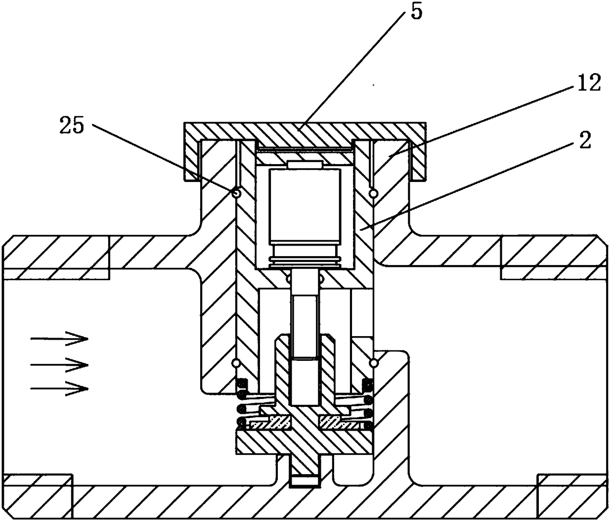
[0059] Embodiment two, according to image 3 Shown:

[0060] On the basis of the first embodiment, the rear end of the valve core 2 is screwed to the extension portion 12 of the valve body 1 . Strengthen the connection between the valve core 2 and the valve body 1 to stabilize the position of the valve core 2 and ensure the sealing.

Embodiment 3

[0062] On the basis of Embodiment 1, when the valve core 2 and the valve body 1 are designed as a whole, the seal rings 1 24 and 2 25 are canceled to reduce the number of parts and the failure rate; it is beneficial to ensure the sealing performance in the valve body 1, Prevent the tight seal caused by the assembly problem of the valve core 2 and the valve body 1.


PUM


Abstract

The invention discloses an electric valve and belongs to the technical field of pipeline valves. The electric valve is characterized in that the electric valve comprises a valve body and a valve element, one side of the valve body is provided with an extension portion connected with the valve body, the extension portion forms a valve element arrangement cavity, an upper baffle and a lower baffle are arranged in the valve body in a connected manner and are opposite to the valve element arrangement cavity, the upper baffle and the lower baffle are arranged on the upper left side of the valve body and the lower right side of the valve body correspondingly and are opposite to the valve element arrangement cavity, the positive-direction projection portions of the left baffle and the right baffle coincide, the left baffle, the right baffle and the valve body define a Z-shaped flow channel, the valve element is located in the valve element arrangement cavity, the front end of the valve element is located in the middle of the Z-shaped flow channel. The electric valve achieves the purposes of being simple in structure, low in cost, suitable for a high-pressure pipe network and stable in seal.

Description

technical field [0001] The invention relates to the technical field of pipeline valves, in particular to an electric valve. Background technique [0002] There are two major problems in the use of traditional solenoid valves in the pipeline network. The first problem is the high cost. When large-scale branch pipeline networks are required, the economic expenditure is too high. The second problem is that they are large in size, especially for high-pressure pipeline networks. The solenoid valve has a large size and takes up a lot of space. [0003] The purpose of the design of the present invention is to design an electric valve with low cost and small size to replace the solenoid valve in the traditional pipe network, and at the same time solve the problem of size, pressure resistance and sealing ability, and repeated opening and closing under the requirement of low cost. Capacity requirements; the invention has low cost, small size, low energy consumption, and can be opened...

Claims


Application Information

Patent Timeline
Patent Type & Authority Applications(China)
IPC IPC(8): F16K1/02F16K1/36F16K1/42
CPCF16K1/02F16K1/36F16K1/427
Inventor 蒋海平
Owner 诸暨市海王消防设备有限公司
Why Eureka
Try Eureka