Supercharge Your Innovation With Domain-Expert AI Agents!

Expansion joint for flue junction of coal-fired power plant

A technology for thermal power plants and joints, applied in the field of expansion joints, can solve problems such as shortening the life of expansion joints and corrosion of expansion joints, and achieve the effects of reducing corrosion, good air tightness and tight connection

Pending Publication Date: 2018-08-24
CHINA HUADIAN ENG
View PDF10 Cites 0 Cited by
  • Summary
  • Abstract
  • Description
  • Claims
  • Application Information

AI Technical Summary

Problems solved by technology

However, the residual urea solution will accumulate in the expansion joint when it passes through the expansion joint at the connection of the flue, causing the expansion joint to be continuously corroded, and the service life of the corroded expansion joint is seriously reduced. Therefore, it is urgent to design an expansion joint to solve the corresponding problem

Method used


Image

  • Expansion joint for flue junction of coal-fired power plant

Examples


Embodiment 1

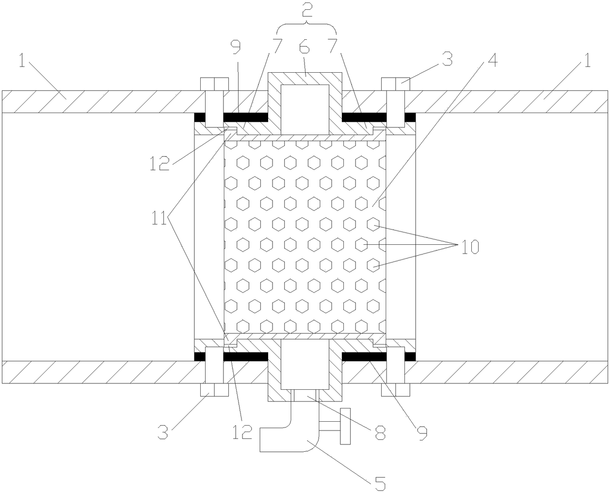
[0018] Embodiment 1 of the present invention: an expansion joint used at the joint of the flue of a thermal power plant, constituted as figure 1 As shown, it includes a body 2, a connector 3, an isolation cover 4 and a faucet 5. The body 2 includes a raised portion 6 and connecting portions 7 located at both ends of the raised portion 6. The raised portion 6 and the connecting portion 7 They are all tubular structures and integrally formed and penetrated. The wall thickness of the raised part 6 and the connecting part 7 is the same. The connecting part 7 is a tubular structure with the same shape as the flue 1, such as a square tube or a round tube. The two connecting parts 7 are respectively connected and communicated with the adjacent flue 1, and the connecting parts 7 and the flue 1 are fixed through the connecting piece 3, and the connecting piece 3 is a bolt, and after the bolt is connected, the expansion joint and the flue The connection between 1 is more stable; an isol...

Embodiment 2

[0020] Embodiment 2: A kind of expansion joint used in the joint of the flue of a thermal power plant, constituted as figure 1 As shown, it includes a body 2, a connector 3, an isolation cover 4 and a faucet 5. The body 2 includes a raised portion 6 and connecting portions 7 located at both ends of the raised portion 6. The raised portion 6 and the connecting portion 7 They are all tubular structures and integrally formed and penetrated. The wall thickness of the raised part 6 and the connecting part 7 is the same. The connecting part 7 is a tubular structure with the same shape as the flue 1, such as a square tube or a round tube. The two connecting parts 7 are respectively connected and communicated with the adjacent flue 1, and the connecting parts 7 and the flue 1 are fixed through the connecting piece 3, and the connecting piece 3 is a bolt, and after the bolt is connected, the expansion joint and the flue The connection between 1 is more stable; an isolation cover 4 is a...


PUM


Abstract

The invention discloses a flue connecting device, in particular to an expansion joint for flue junction of a coal-fired power plant. The expansion joint comprises a body, connecting pieces, an isolation hood and a faucet, wherein the body comprises a bump part and connecting parts respectively positioned at the two ends of the bump part, and the bump part and the connecting part are integrally formed and interconnected; the two connecting parts are respectively connected with adjacent flues and communicate with the flues, and each connecting part and each flue are fixed through the connectingpiece; the isolation hood is arranged between the two connecting parts; and a liquid outlet is formed in the bottom of the bump part, and the faucet is connected in the liquid outlet. The expansion joint can compensate for deformation between the flues, so that the adjacent flues can be connected more stably. Moreover, the corrosion of the expansion joint from corrosive liquid is reduced, and thecorrosion resistance of the expansion joint is enhanced, so that the expansion joint is more durable.

Description

technical field [0001] The invention relates to a flue connection device, in particular to an expansion joint used for the connection of the flue in a thermal power plant. Background technique [0002] Boiler flue gas in thermal power plants contains a large amount of nitrogen oxides. If emission control is not carried out, it will cause air pollution and acid rain and other disasters. In response to the national call for energy conservation and emission reduction, many thermal power plants have strictly controlled the emission of nitrogen oxides, and the nitrogen oxides in the boiler flue gas are mainly removed through the flue gas denitrification reaction. Flue gas denitrification often sprays urea solution in the flue containing high-temperature flue gas. The urea solution can perform denitrification reaction with nitrogen oxides in the flue gas at high temperature, thereby removing nitrogen oxides, saving energy, reducing emissions, and reducing environmental pollution. ...

Claims


Application Information

Patent Timeline
IPC IPC(8): F16L51/00F16L55/24
CPCF16L51/00F16L55/24
Inventor 赵利兴杨亚东陈聪
Owner CHINA HUADIAN ENG
Features
  • R&D
  • Intellectual Property
  • Life Sciences
  • Materials
  • Tech Scout
  • Unparalleled Data Quality
  • Higher Quality Content
  • 60% Fewer Hallucinations
Learn More