
Top water-drainage device for gas exhaust chimney for industrial hazardous waste incineration

A technology for hazardous waste and exhaust chimneys, which is applied to exhaust gas devices, combustion methods, and treatment of combustion products. It can solve the problems of flue gas condensed water corroding the outer wall of the chimney, and achieve the effect of prolonging the service life.

Pending Publication Date: 2018-08-24
TIANJIN UNIV
View PDF0 Cites 10 Cited by
  • Summary
  • Abstract
  • Description
  • Claims
  • Application Information

AI Technical Summary

Problems solved by technology

[0003] The purpose of the present invention is to overcome the deficiencies of the prior art and provide a drainage device at the top of an industrial hazardous waste incineration exhaust chimney to solve the problem of corroding the outer wall of the chimney by the condensed water of the flue gas

Method used


Image

  • Top water-drainage device for gas exhaust chimney for industrial hazardous waste incineration
  • Top water-drainage device for gas exhaust chimney for industrial hazardous waste incineration
  • Top water-drainage device for gas exhaust chimney for industrial hazardous waste incineration

Examples


Embodiment 1

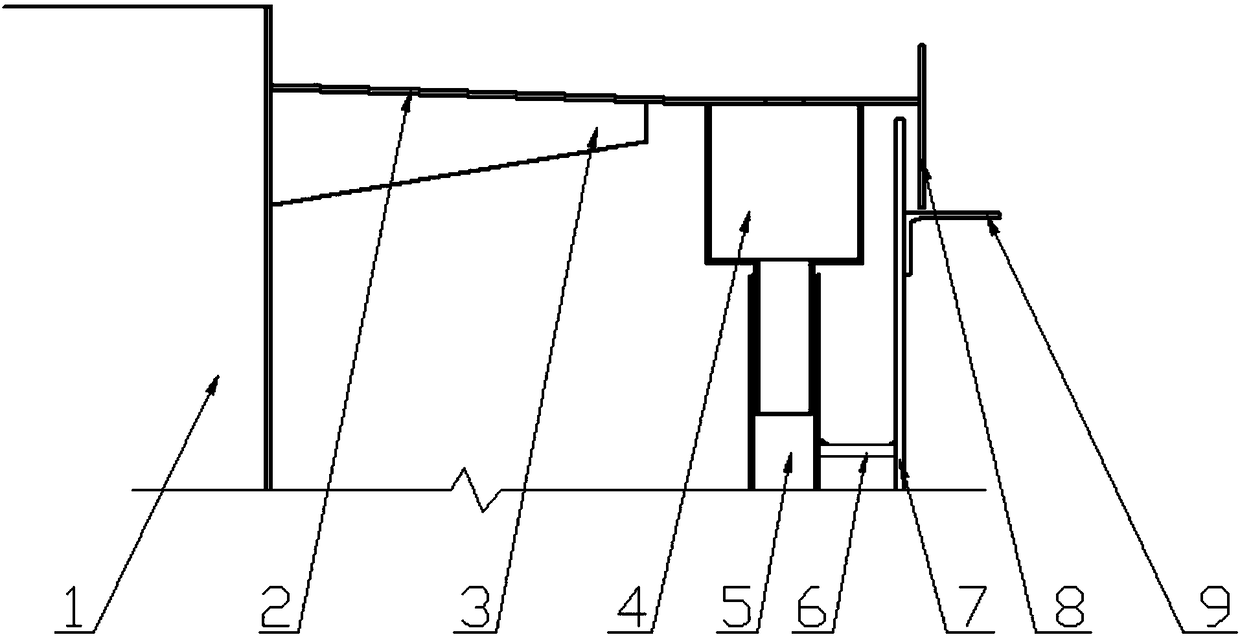
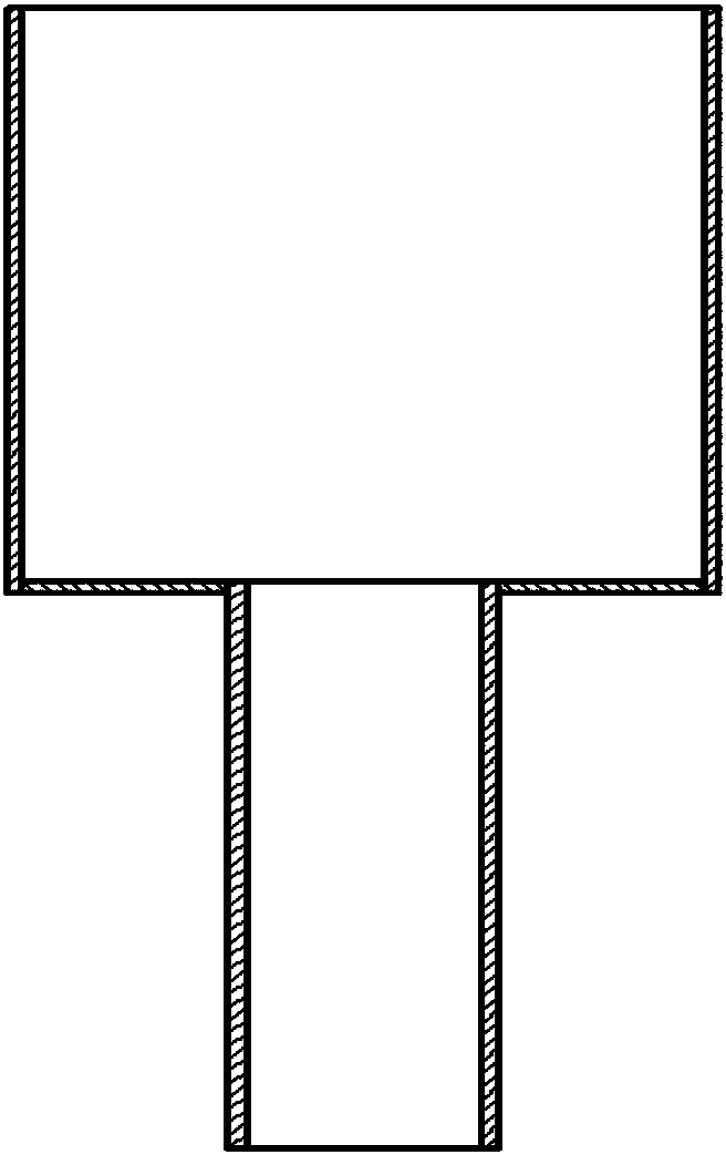
[0024] A drainage device at the top of an industrial hazardous waste incineration exhaust chimney, which adopts the method of centralized collection and separate transportation to isolate the flue gas condensed water from direct contact with the chimney cylinder, mainly including a jacket cover plate 2, a water collector 4, and a water retaining plate 8;

[0025] The present invention is arranged between the jacket of chimney inner cylinder 1 and outer cylinder 7, as figure 1 The outer wall of the chimney inner tube 1 shown is provided with a jacket cover plate 2, and the jacket cover plate 2 in this embodiment is arranged at a place 100 ± 5 mm lower than the top of the chimney inner tube 1. The surface structure of the cover plate 2 is mainly composed of any one of horizontal, inclined or concave, or mainly composed of any one of micro-U, U-shaped, V-shaped or micro-V-shaped. In this embodiment, the jacket cover The surface structure of the plate 2 is inclined, and it inclin...

Embodiment 2

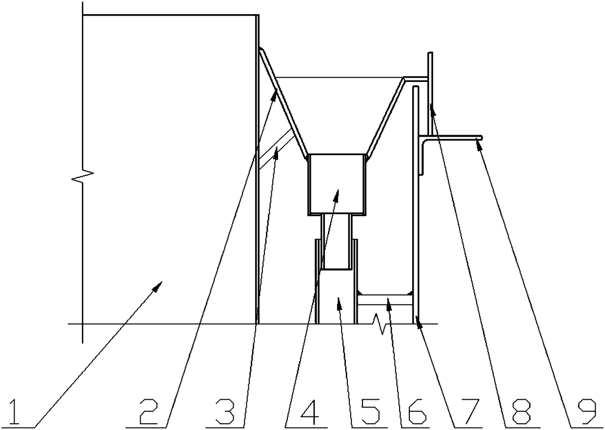
[0029] The drainage device at the top of the industrial hazardous waste incineration exhaust chimney collects the condensed water of the flue gas through the condensed water collection mechanism. Under different working conditions, different structural types of jacketed covers can be used to obtain corresponding effects.

[0030] The jacketed cover plate with horizontal surface structure is suitable for the case where the condensed water produced in the flue gas discharge is relatively small, the average annual precipitation in the operating climate is small, and the jacket between the jacketed chimneys is greater than 500 mm. Condensate can be collected quickly and efficiently.

[0031] When the annual average precipitation is large and the jacket volume is less than 500 mm, the contact area between the jacket cover plate and the flue gas is small, and the condensed water cannot be collected effectively. The jacket cover plate with V-shaped surface structure is as follows: i...


PUM


Abstract

The invention relates to a top water-drainage device for a gas exhaust chimney for industrial hazardous waste incineration, and the top water-drainage device is arranged between a chimney inner barreland a jacket of an outer barrel. The top water-drainage device is characterized in that a jacket cover plate is arranged on the outer wall of the chimney inner barrel, wherein the tail end of the jacket cover plate is connected with a water stop plate; the water stop plate is arranged at the outer side of the chimney outer barrel; the jacket cover plate and the water stop plate are taken as an integer to freely move along with thermal-expansion and cold-contraction of the chimney inner barrel; and a water collector is arranged on the bottom of the jacket cover plate. The top water-drainage device can effectively prevent liquid with corrosion from corroding the chimney inner barrel and the chimney outer barrel.

Description

technical field [0001] The invention belongs to the technical field of collecting condensed water from industrial hazardous waste incineration flue gas discharge, and relates to a novel hazardous waste incineration exhaust chimney top drainage device, which is suitable for use in environments where the flue gas emitted by double-layer exhaust chimneys contains corrosive flue gas. Specifically, it is a drainage device at the top of an industrial hazardous waste incineration exhaust chimney. Background technique [0002] At present, when my country's industrial hazardous waste is incinerated and the exhaust gas is discharged in accordance with the national emission standards, the exhausted flue gas has a high steam content, and the chimney is a double-layer chimney. The inner cylinder of the chimney is in direct contact with the flue gas to prevent corrosion, and the outer cylinder plays a supporting role. The steam in the flue gas contacts with the air to form condensed wate...

Claims


Application Information

Patent Timeline
IPC IPC(8): F23J13/00
CPCF23J13/00
Inventor 孙袭明赵林
Owner TIANJIN UNIV
Learn More