Beam forming method based on covariance matrix reconstruction and steering vector correction

A technology of covariance matrix and steering vector, which is applied in the direction of measuring device, radio wave measurement system, radio wave reflection/re-radiation, etc. Variance matrix mismatch and other issues, achieve low performance requirements, achieve performance requirements, and good robustness

Inactive Publication Date: 2018-08-24
NANJING UNIV OF SCI & TECH
View PDF5 Cites 15 Cited by
  • Summary
  • Abstract
  • Description
  • Claims
  • Application Information

AI Technical Summary

Problems solved by technology

Beamformer performance degrades severely when the training data contains signals of interest resulting in mismatched covariance matrices or mismatched steering vectors
In order to improve the robustness of the beamformer to the covariance matrix mismatch, the diagonal loading algorithm artificially introduces white noise on the diagonal of the sampled data covariance matrix, making it closer to the ideal interference plus noise covariance matrix, and also That is, adding a regularization term to the objective function of the minimum variance distortion free response (MVDR) beamformer, but this method lacks a rigorous theoretical basis for selecting the optimal loading level and the robustness to steering vector mismatch is not improved
The eigenspace-based beamforming algo

Method used


Image

  • Beam forming method based on covariance matrix reconstruction and steering vector correction
  • Beam forming method based on covariance matrix reconstruction and steering vector correction
  • Beam forming method based on covariance matrix reconstruction and steering vector correction

Examples


Embodiment

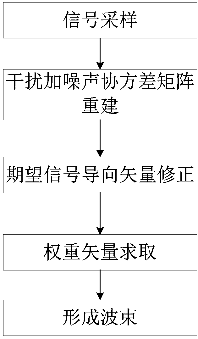
[0052] figure 1 Contains the process flow chart of obtaining the array weight vector by adopting the present invention. The number of array elements is 16, the sidelobe constrained area is [-90°,-12°]∪[12°,90°], and the desired signal angle is 0°. to combine figure 1 , the present invention is based on the beamforming method of covariance matrix reconstruction and steering vector correction, comprising the following steps:

[0053] Step 1, sampling the received signal of the radar array to obtain the received signal vector;

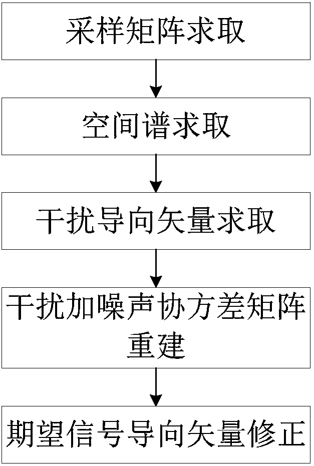
[0054] Step 2. According to the received signal vector sampled in step 1, the received data covariance matrix and spatial spectrum distribution are obtained, and then the interference steering vector is obtained by the spherical constraint method, and then the interference plus noise covariance matrix is ​​reconstructed;

[0055] Among them, the specific process of rebuilding the interference plus noise covariance matrix is:

[0056] The Capon space s...


PUM


Abstract

The invention discloses a beam forming method based on covariance matrix reconstruction and steering vector correction. The method comprises steps of (1) sampling a received signal of a radar array toobtain a received signal vector; (2) according to the sampled received signal vector, obtaining a received data covariance matrix and a spatial spectral distribution, and then obtaining an interference steering vector by a spherical constraint method, and reconstructing an interference-noise covariance matrix; (3) correcting a desired signal steering vector according to the reconstructed interference-plus noise covariance matrix; (4) according to the reconstructed covariance matrix and the corrected desired signal steering vector, solving a MVDR model with added side lobe constraints by a convex optimization method to obtain a global optimal weight vector; and (5) multiplying the received signal vector by the global optimal weight vector to obtain a robust low-sidelobe adaptive beam. Thebeam forming method of the present invention not only has good robustness but also has low side lobes.

Description

technical field [0001] The invention belongs to the technical field of adaptive digital beam forming of digital array radar, in particular to a beam forming method based on covariance matrix reconstruction and steering vector correction. Background technique [0002] Adaptive beamforming technology has been widely used in wireless communication, radar, sonar, medical imaging, radio astronomy and other fields. Conventional adaptive beamforming assumes that the exact knowledge of the steering vector of the desired signal is known, but in practice the performance of beamforming is affected by errors, resulting in a serious decline in the performance of the beamformer. In order to correct the deviation, robust adaptive beamforming technology came into being. [0003] For the design of an adaptive beamformer with excellent performance, robustness, sidelobe level control, and interference suppression should be considered, so some technical measures will be used to achieve this goa...

Claims


Application Information

Patent Timeline
IPC IPC(8): G01S13/89
CPCG01S13/89
Inventor 谢仁宏陈颖李勇芮义斌李鹏郭山红张天乐袁小琦
Owner NANJING UNIV OF SCI & TECH
Why Eureka
Try Eureka