Visible light image sea antenna detection method based on energy seam cutting and RANSAC fitting

A sea-antenna detection and visible light technology, which is applied in image enhancement, image analysis, image data processing, etc., can solve the problems of sea-antenna slow speed, large data volume, and low efficiency, and achieve the effect of speed improvement

Inactive Publication Date: 2018-08-24
HARBIN INST OF TECH
View PDF5 Cites 2 Cited by
  • Summary
  • Abstract
  • Description
  • Claims
  • Application Information

AI Technical Summary

Problems solved by technology

[0004] The purpose of the present invention is to solve the problems of slow speed and low efficiency of sea antenna detection in traditional methods, which lead to difficult operati...

Method used


Image

  • Visible light image sea antenna detection method based on energy seam cutting and RANSAC fitting
  • Visible light image sea antenna detection method based on energy seam cutting and RANSAC fitting
  • Visible light image sea antenna detection method based on energy seam cutting and RANSAC fitting

Examples


specific Embodiment approach 1

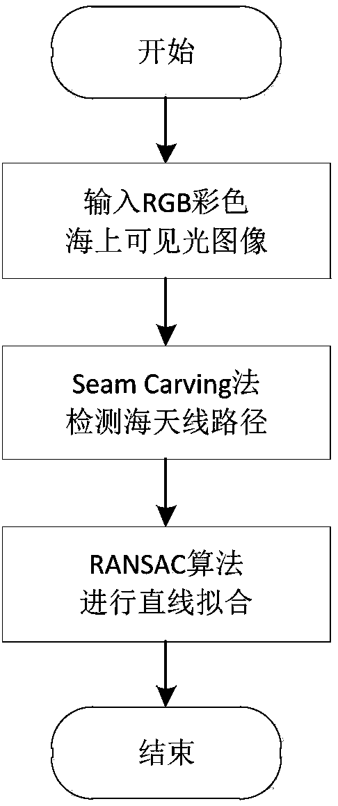
[0036] Specific implementation mode one: as figure 1 and figure 2 As shown, a sea antenna detection method based on energy seam cutting (Seam Carving) and RANSAC fitting includes the following steps:

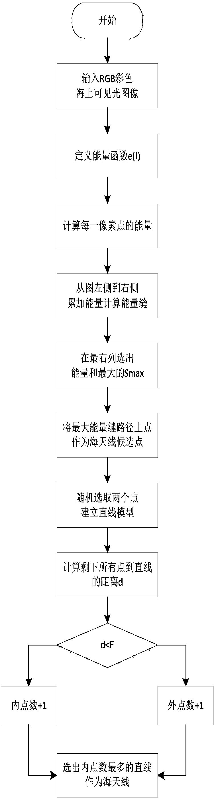
[0037] Step 1. Process an RGB color visible light image to find the energy seam with the highest energy in the image;

[0038] In order to better perceive the specific content in the image, an energy function is defined to specifically describe each pixel of the image. In an image, if a point is quite different from its surroundings, gradients are often used to describe this feature. When defining the energy function, parameters such as gradient value, visual salience and entropy can be selected for use to represent, and in the present invention, the square root of the sum of squares of gradients in the x direction and the y direction is selected for calculation;

[0039] Step 11, calculating the energy value of each pixel of the input RGB color visible light image (m×n);

...

specific Embodiment approach 2

[0056] Specific embodiment two: the difference between this embodiment and specific embodiment one is: the calculation process of the energy value of each pixel in the step one by one is:

[0057] Calculate and add each pixel of the R, G, and B channels using formula (3):

[0058]

[0059] Where e(I) is the energy value of the pixel point, I i is the pixel value of the i-th channel, is the gradient of the image in the horizontal direction x, is the gradient in the vertical direction y of the image.

[0060] Other steps and parameters are the same as those in Embodiment 1.

specific Embodiment approach 3

[0061] Specific embodiment three: the difference between this embodiment and specific embodiment one or two is: the calculation process of the energy value of each pixel in the step one by one is:

[0062] The input RGB color visible light image is first converted into a grayscale image and then calculated, as shown in formula (4):

[0063]

[0064] where I is a grayscale image.

[0065] Other steps and parameters are the same as those in Embodiment 1 or Embodiment 2.


PUM


Abstract

A visible light image sea antenna detection method based on energy seam cutting and RANSAC fitting is disclosed. The invention relates to the visible light image sea antenna detection method. By usinga traditional method, the speed of sea antenna detection is slow and efficiency is low so that operation in later-period image processing is difficult and a data size is large. By using the method ofthe invention, the above problems are solved. The method comprises the following steps of 1, processing an RGB color visible light image and finding the energy seam of highest energy in the image; and 2, using an RANSAC method to fit a sea antenna candidate point and acquiring a sea antenna. In the invention, the most important connection path in a visible light image is detected. A pixel point in the path is taken as the sea antenna candidate point, an RANSAC algorithm is used to carry out straight line fitting on the candidate point, the offset of the sea antenna caused by the outer pointsof a noise point, a target edge and the like is successively eliminated so that the detection speed of the sea antenna is increased by about 10% and an accuracy detection rate is above 90%. The methodis used for the image processing field.

Description

technical field [0001] The invention relates to a sea antenna detection method of a visible light image. Background technique [0002] In the case of looking at the sea surface to the end of the sea and sky, the acquired sea image can usually be divided into three parts: the sky part, the sea surface part and the sea antenna part between them. The straight line at the junction of the sea and the sky is called the sea line. If there is a target at a relatively long distance appearing on the sea surface, it will definitely break the linearity of the sea antenna. Using this feature, we can quickly determine whether there is a target in the distance by accurately finding out the location of the sea antenna, and reduce the calculation range in the later image processing process. Not only that, the interference of ocean noise and sky noise existing outside the sea antenna area can be effectively eliminated. As the cornerstone of maritime target detection and recognition, the se...

Claims


Application Information

Patent Timeline
IPC IPC(8): G06T7/12G06T7/143
CPCG06T2207/20076G06T2207/20132G06T2207/30184G06T7/12G06T7/143
Inventor 任广辉魏俊杰何胜阳熊阿龙樊如愿王昭张宇鹏李锦江
Owner HARBIN INST OF TECH
Why Eureka
Try Eureka