Anti-magnetic bias circuit and method for inverter power supply

An anti-bias circuit, inverter power supply technology, applied in emergency protection circuit devices, electrical components, output power conversion devices, etc., can solve the problems of main power tube damage, main power tube overcurrent damage, etc. oversized effect

Active Publication Date: 2018-08-24
BEIHANG UNIV
View PDF4 Cites 2 Cited by
  • Summary
  • Abstract
  • Description
  • Claims
  • Application Information

AI Technical Summary

Problems solved by technology

That is to say, 1~2us delay to turn off, the current will increase sharply by tens of amperes or even hundreds of amperes, which will easily cause overcurrent damage to the main power tube
Therefore, if the control circuit

Method used


Image

  • Anti-magnetic bias circuit and method for inverter power supply
  • Anti-magnetic bias circuit and method for inverter power supply
  • Anti-magnetic bias circuit and method for inverter power supply

Examples


Example Embodiment

[0053] The implementation of the present invention will be described in detail below with reference to the accompanying drawings and embodiments, so as to fully understand how the present invention applies technical means to solve technical problems and achieve the realization process of technical effects and implement them accordingly. It should be noted that, as long as there is no conflict, each embodiment of the present invention and each feature in each embodiment can be combined with each other, and the technical solutions formed are all within the protection scope of the present invention.

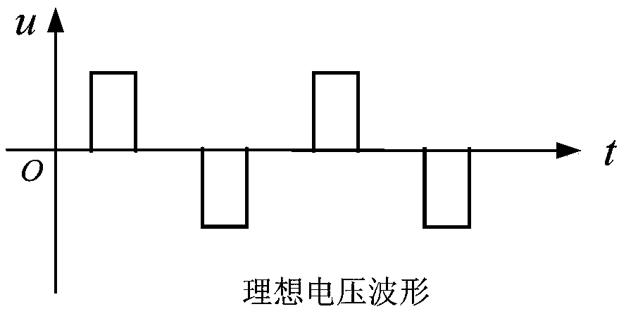
[0054] In an ideal inverter power supply, if the voltage waveform loaded on its transformer is like image 3 , The corresponding ideal magnetic working state of the main transformer is as Figure 4 , The magnetic flux works symmetrically around the origin; if bias occurs, its magnetic working state is like Figure 5 As shown, the center point of the balanced work of the magnetic flux is ...


PUM


Abstract

The invention discloses an anti-magnetic bias circuit and method for an inverter power supply. The circuit comprises a PWM module configured to output a pulse synchronization signal and two original half-wave pulse width modulation signals; a comparison module configured to judge whether a magnetic bias of a main transformer of the inverter power supply occurs; a PWM output control module configured to output a PWM control signal to the PWM module based on the pulse synchronization signal and a comparison result output by the comparison module when a magnetic bias of the main transformer of the inverter power supply occurs; and a PWM pulse width adjusting module configured to generate an anti-magnetic bias pulse width modulation signal having a pulse width larger than that of the originalhalf-wave pulse width modulation signal, and output to an inverter circuit of the inverter power supply to control the magnetic bias state of the inverter power supply. The anti-bias circuit providedby the invention can suppress the magnetic bias state of the main transformer and realize overcurrent protection for a main power tube.

Description

technical field [0001] The invention belongs to the technical field of power electronic inverter power supply, and in particular relates to an anti-bias circuit and method for inverter power supply. Background technique [0002] Due to the characteristics of high efficiency, energy saving, small size, light weight and excellent performance, the inverter power supply technology has been widely used in arc welding power supply, DC regulated power supply, charger and other fields, and has become the mainstream technology in today's high-power power supply . At present, most high-power power supplies use full-bridge or half-bridge conversion main circuits to realize inverter conversion. Typical circuit types are as follows: figure 1 shown. [0003] During the operation of the bridge circuit, due to the impossibility of absolute symmetry and consistency of the pulse width modulation and circuit parameters, voltage fluctuations and other reasons, the positive and negative half-w...

Claims


Application Information

Patent Timeline
IPC IPC(8): H02M1/32H02M1/40H02H7/122
CPCH02H7/1225H02M1/32H02M1/40
Inventor 齐铂金张伟
Owner BEIHANG UNIV
Why Eureka
Try Eureka