A power division isolation filter circuit
An isolation filter and isolation resistance technology, applied in the field of electronics, can solve the problems of large harmonic component energy, easy generation of electromagnetic compatibility, and deterioration of system noise, so as to suppress harmonic components, solve problems in electromagnetic compatibility, and improve system noise. Effect
- Summary
- Abstract
- Description
- Claims
- Application Information
AI Technical Summary
Problems solved by technology
Method used
Image
Examples
Embodiment 1
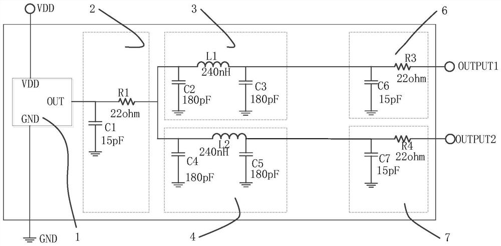
[0028] Such as figure 2 As shown, a power division isolation filter circuit includes: an active crystal oscillator 1, a main port CR matching unit 2, a first CLC filter unit 3, a second CLC filter unit 4, a first CR matching unit 6 and a second CR matching unit Unit 7; the active crystal oscillator 1 is connected to the main port CR matching unit 2, the main port CR matching unit 2 is connected to the input end of the first CLC filter unit 3 and the input end of the second CLC filter unit 4, and the first CLC filter unit 3 The output end of the first CR matching unit 6 is connected to the input end, the output end of the second CLC filter unit 4 is connected to the input end of the second CR matching unit 7, and the output end of the first CR matching unit 6 is connected to the circuit output end OUTPUT1 The output end of the second CR matching unit 7 is connected to the circuit output end OUTPUT2.
[0029] Specifically, the main port CR matching unit 2 includes a capacitor ...
Embodiment 2
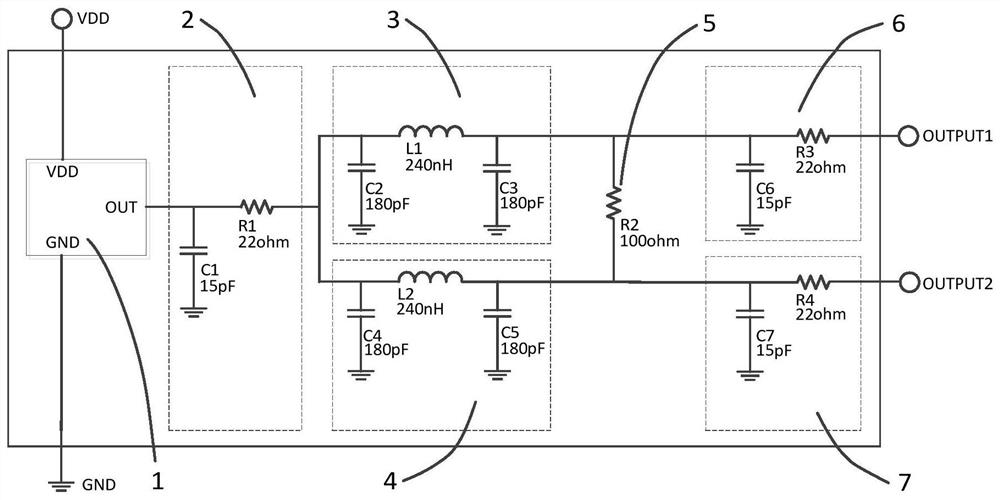
[0038] Such as image 3 As shown, the difference between Embodiment 2 and Embodiment 1 is that: the output end of the first CLC filter unit 3 and the output end of the second CLC filter unit 4 are connected through an isolation resistor 5, and the first CR matching unit 6 and the second CR matching The unit 7 is also connected through the isolation resistor 5, that is, one end of the isolation resistor 5 is connected to one end of the capacitor C3 of the first CLC filter unit 3 and the other end of the inductor L1, and one end of the capacitor C6 of the first CR matching unit 6 and one end of the resistor R3 Connection; the other end of the isolation resistor 5 is connected with one end of the capacitor C5 of the second CLC filter unit 4 and the other end of the inductor L2, one end of the capacitor C7 of the second CR matching unit 7 and one end of the resistor R4, when there is a clutter signal When entering the circuit of the present invention from the circuit output termin...
Embodiment 3
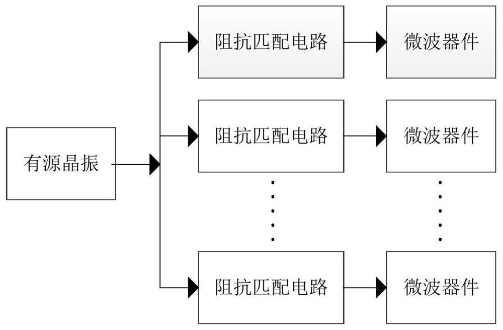
[0040] Such as Figure 4 As shown, the difference between the third embodiment and the first embodiment is that the circuit output terminal OUTPUT1 and the circuit output terminal OUTPUT2 can be connected to the first CLC filter unit, the second CLC filter unit, the first CR matching unit and the second CR matching unit. The power division isolation filter circuit uses a cascading method to increase the output terminal of the active crystal oscillator signal, thereby connecting multiple microwave integrated devices, making the power division isolation filter circuit more widely used.
[0041] To sum up, the embodiment of the present invention provides a power division isolation filter circuit through the matching unit and the filter unit to solve the problems of poor anti-interference ability and inability to optimize the system noise of the existing clock shunt circuit, which can be effectively applied to automobile collision avoidance Radar system, improve radar performance....
PUM
 Abstract
Description
Claims
Application Information
 - R&D
- Intellectual Property
- Life Sciences
- Materials
- Tech Scout
- Unparalleled Data Quality
- Higher Quality Content
- 60% Fewer Hallucinations
Browse by: Latest US Patents, China's latest patents, Technical Efficacy Thesaurus, Application Domain, Technology Topic, Popular Technical Reports.
© 2025 PatSnap. All rights reserved.Legal|Privacy policy|Modern Slavery Act Transparency Statement|Sitemap|About US| Contact US: help@patsnap.com


