Wheel axle type particle accelerator energy reducing device and energy reducing method in vacuum

A particle accelerator and energy reduction technology, which is applied in accelerators, electrical components, etc., can solve the problems of high positioning accuracy, insufficient compactness of the energy reducer, and large increase in emissivity, so as to avoid excessive growth, compact structure, The effect of easy operation

Inactive Publication Date: 2018-08-24
NORTHWEST INST OF NUCLEAR TECH
View PDF15 Cites 1 Cited by
  • Summary
  • Abstract
  • Description
  • Claims
  • Application Information

AI Technical Summary

Problems solved by technology

This kind of energy reducer can realize the continuous adjustment of energy. The disadvantage is that it requires high positioning accuracy; After multiple scattering, the emittance increases greatly and the transmission efficiency is low
[0007] The advantage of the energy reduction device based on the rotating mechanism is that it is relatively compact, and more stops can be arranged on a rotating disk to realize the adjustment of multiple energy gears. The difficulty is that it involves rotating motion in a vacuum, which is more complicated to implement.

Method used


Image

  • Wheel axle type particle accelerator energy reducing device and energy reducing method in vacuum
  • Wheel axle type particle accelerator energy reducing device and energy reducing method in vacuum
  • Wheel axle type particle accelerator energy reducing device and energy reducing method in vacuum

Examples


Embodiment Construction

[0036] In order to make the object, technical solution and advantages of the present invention clearer, the present invention will be further described in detail below in conjunction with the accompanying drawings and embodiments.

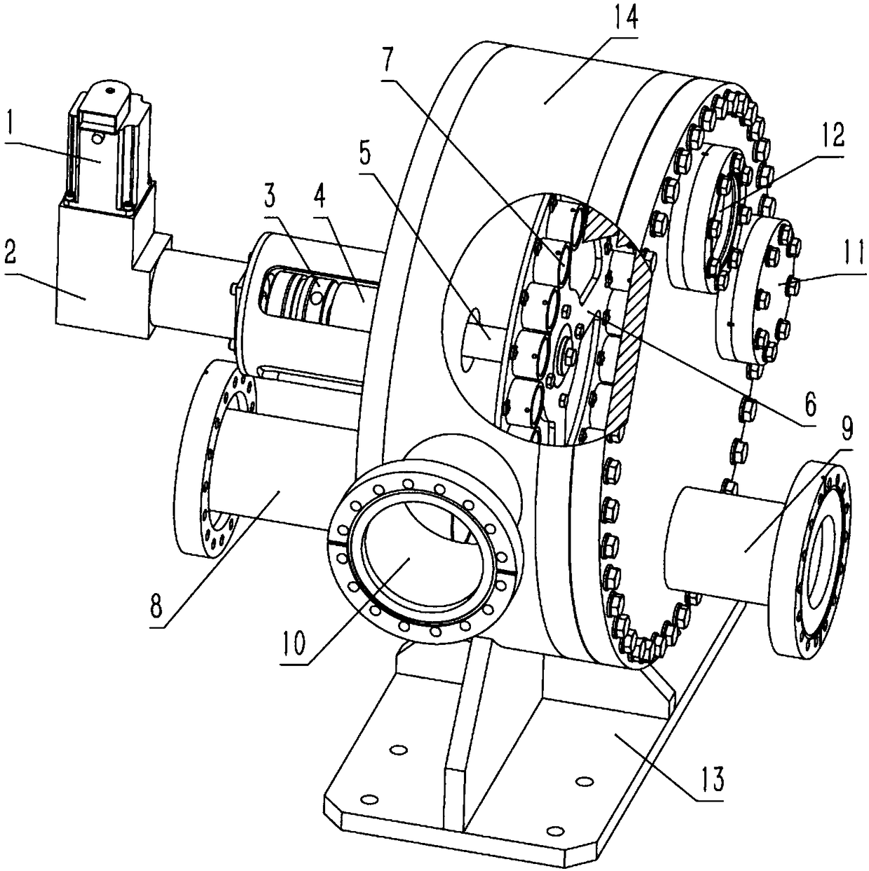
[0037] From figure 1 It can be seen that the energy reducing device in this embodiment mainly includes a rotary drive mechanism, a vacuum chamber 14 and an energy reducing turntable located inside the vacuum chamber 14;

[0038] The rotary drive mechanism includes a servo motor 1, a reducer 2 and a magnetic fluid seal transmission device 4;

[0039] The input shaft of the reducer 2 is connected with the output shaft of the servo motor 1, the output shaft of the reducer 2 is connected with the central shaft 5 of the magnetic fluid seal transmission 4 through the coupling 3, and the central shaft 5 of the magnetic fluid seal transmission 4 passes through The vacuum cavity 14 is connected with the energy-reducing turntable; the magnetic fluid sealin...


PUM


Abstract

The invention belongs to the technical field of particle accelerators, and relates to a passive energy reducer device for regulating the energy of particles extracted from an accelerator, in particular to a wheel axle type particle accelerator energy reducing device and energy reducing method which can be used in vacuum. The energy reducer includes a rotary driving mechanism, a rotary disk on which a plurality of energy reducing stop blocks are mounted and a vacuum system. The vacuum system enables the rotary disk and the energy reducing stop blocks to be in a vacuum environment, and the rotary disk is rotated through the rotary driving mechanism, thereby changing the thickness of the energy reducing stop blocks at a beam position to realize energy adjustment. The energy reducer has a compact structure, which is in favor of miniaturization; a magnetic fluid sealing transmission device is adopted, and thus vacuum reliability is high; a wheel axle type structure is adopted, rapid adjustment of different energy can be realized; the energy reducing stop blocks are convenient to dismount, thereby facilitating replacement; and the energy reducing method is a non-superposition type energyreducing method, and has little influence on beam emittance.

Description

technical field [0001] The invention belongs to the technical field of particle accelerators, and relates to a passive energy reducer device for adjusting the energy of particles extracted from an accelerator, in particular to a wheel-shaft particle accelerator energy reducer and its energy reduction method that can be used in vacuum. Background technique [0002] In the field of particle accelerator technology, especially in the field of cyclotrons and linear accelerators with fixed energy, a passive energy reduction device based on the principle of energy loss due to the interaction between particles and matter is often used. In synchrotrons, since accelerators often have a minimum extraction energy, such passive energy reduction devices are sometimes used. [0003] The core of this energy-reducing device is a material block of different thickness. When a beam of specific energy passes through a material block of different thickness, the energy lost through ionization and ...

Claims


Application Information

Patent Timeline
Patent Type & Authority Applications(China)
IPC IPC(8): H05H7/12
CPCH05H7/12H05H2007/125
Inventor 王忠明屈二渊王敏文王迪陈伟邱孟通
Owner NORTHWEST INST OF NUCLEAR TECH
Why Eureka
Try Eureka