Pipeline system and construction method thereof

A pipeline system and construction method technology, applied in tunnels, tunnel linings, earthwork drilling and other directions, can solve the problems of increasing construction time, delaying construction progress, and small lateral stiffness, reducing construction time, enhancing anchoring capacity and waterproofing capacity. , the effect of reducing resistance and stress

Active Publication Date: 2018-08-28
丰泽智能装备股份有限公司
View PDF12 Cites 0 Cited by
  • Summary
  • Abstract
  • Description
  • Claims
  • Application Information

AI Technical Summary

Problems solved by technology

[0003] The current waterstop is less rigid in the lateral direction and is easy to bend
The construction quality of the waterstop is also an important part of tunnel waterproofing. At present, during the construction of the waterstop, one side of the waterstop is erected, the other side is suspended, and the "end" of the waterstop is flat with steel clips. It ensures that the waterstop will not sag or deform during construction, but it increases the construction time, delays the construction progress, and virtually increases the construction cost, and the waterstop is in direct contact with the steel bar, which causes the gap between the waterstop and the steel bar It is difficult to compact the concrete between the waterstop and the steel bar, and the concrete between the waterstop and the steel bar is also prone to cracks and pores during the process of marking, which affects the construction quality and increases the hidden danger of water leakage
Remove the steel clips, the waterstop will easily sag and deform due to its own gravity, and in the process of pouring concrete, the waterstop will also shift due to the impact, flow and vibration of the concrete. In this way, it cannot be guaranteed that the anchor end of the waterstop can be fully anchored in the concrete, causing the waterstop to fail to fully exert its waterproof function
Since there is no adhesive force between the rubber of the waterstop and the concrete, the concrete at the joint will become thinner after the waterstop is shifted, causing the phenomenon of "dropping blocks", which seriously affects driving safety
[0004] When the waterstop is produced and vulcanized, in order to ensure the appearance quality of the waterstop and prevent rubber shortage, the sum of the upper and lower semi-finished films between the molds is greater than the thickness of the mold cavity, and the rubber is in a fluid state when it is pressurized and heated. The rubber needs to flow out from the delivery end of the mold, and at the same time it will drive the reinforcement plate to change its original position, resulting in too large spacing between the reinforcement plates and unqualified products

Method used


Image

  • Pipeline system and construction method thereof
  • Pipeline system and construction method thereof
  • Pipeline system and construction method thereof

Examples


Embodiment 1

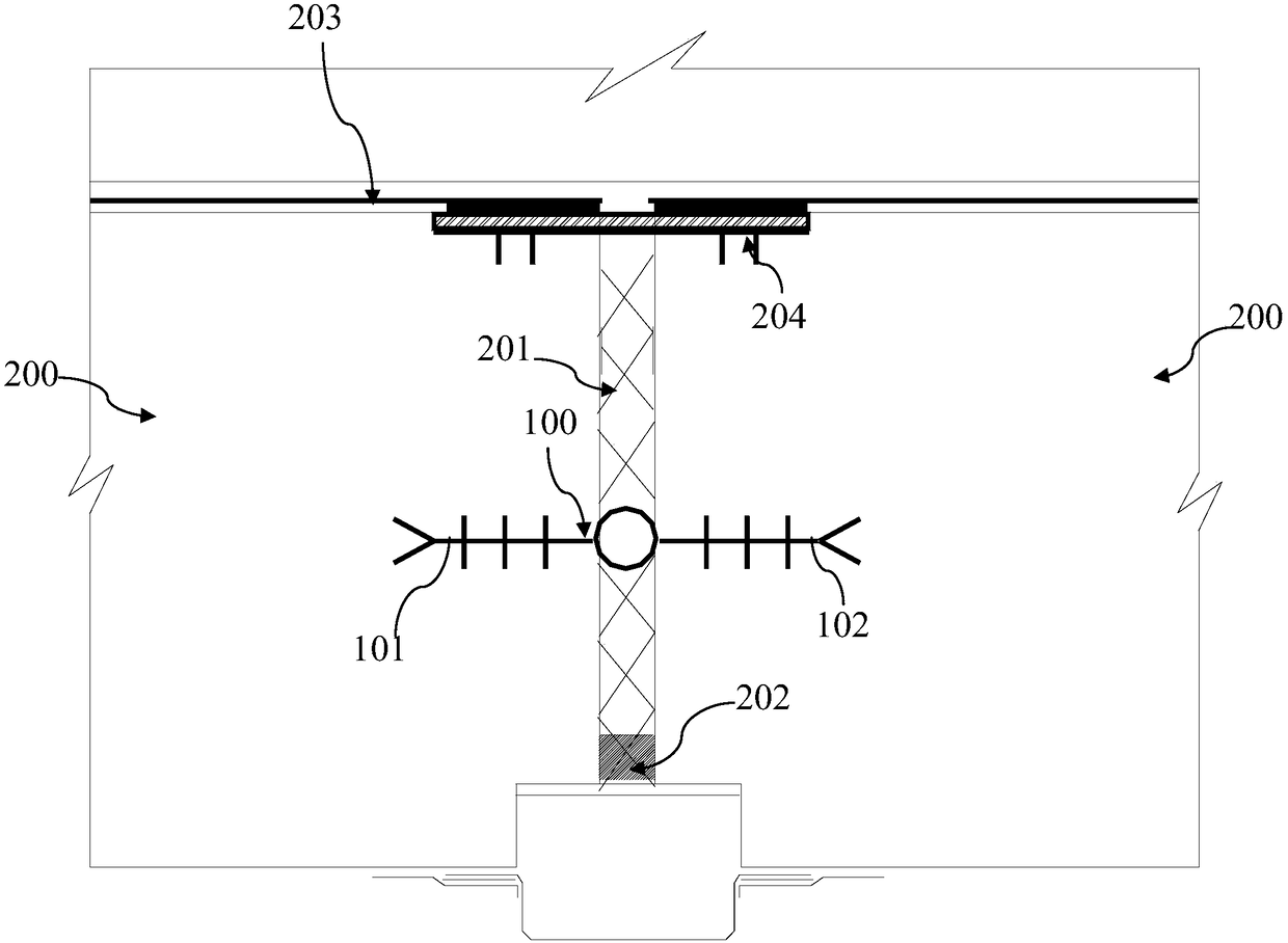
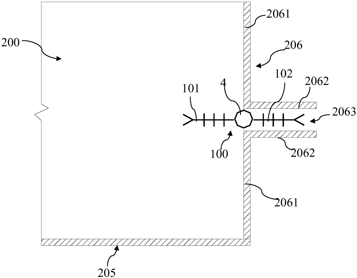
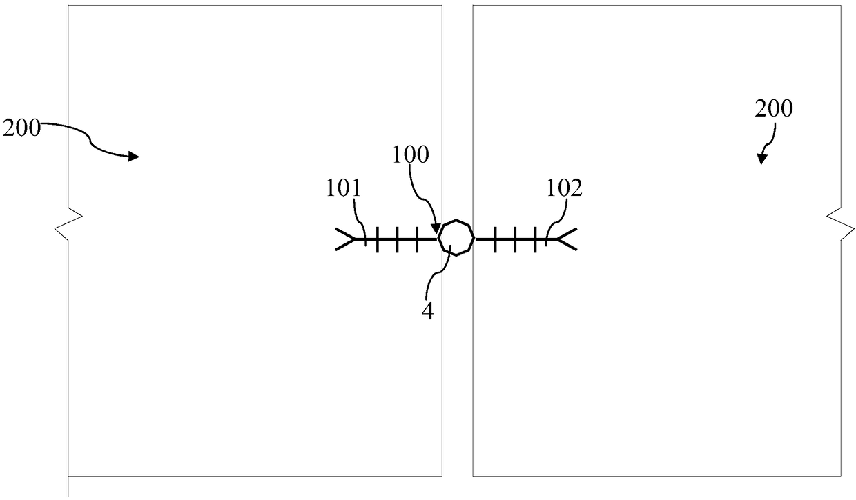
[0053] Such as figure 1 and Figure 3-5 As shown, the pipeline system provided in this embodiment includes at least two sections of adjacent liner pipes 200 , and a rubber waterstop 100 is arranged between any two sections of adjacent liner pipes 200 .

[0054] The rubber waterstop 100 includes a waterstop body 2 , and the waterstop body 2 surrounds the pipe walls of two adjacent sections of the liner 200 .

[0055] Wherein, along the width direction of the waterstop body 2 , two sides of the waterstop body 2 respectively have clips 1 , and the clips 1 on each side are respectively poured into the pipe wall of a section of the liner 200 .

[0056] A plurality of reinforcement plates 3 are arranged at intervals along the circumferential direction of the waterstop body 2 inside the waterstop body 2 .

[0057] Wherein, there is a distance between any two adjacent reinforcing plates 3 , and each reinforcing plate 3 extends along the width direction of the waterstop body 2 .

[00...

Embodiment 2

[0068] Such as Figure 4-5 As shown, the horizontally reinforced mid-buried rubber waterstop in the present invention includes a waterstop body 2 with chucks 1 on both sides, and stiffening plates 3 are arranged at intervals inside the waterstop body 2 , and between the stiffening plates 3 The spacing distance is 2-7 times of the width of the stiffening plate 3. Stiffeners are installed inside to provide lateral rigidity for the waterstop. During the construction process, especially during the pouring of concrete, it is ensured that the waterstop remains horizontal without external devices, which enhances the waterstop. The anchoring ability and waterproof ability of the belt also reduce the construction time of the installation device and eliminate the safety hazard of "dropping blocks"; the controllability of the spacing of the stiffening plates can be adjusted by changing the spacing of the stiffening plates to adjust the lateral stiffness. Size, so as to meet the construc...

Embodiment 3

[0071] Such as figure 1 , image 3 and Figure 6-7 As shown, a deformable deformation ring 4 is provided on the waterstop body 2, and a reinforcement plate bending section 5 is correspondingly provided on the reinforcement plate 3 corresponding to the deformation ring 4, and the reinforcement plate bending section 5 is located in the deformation ring 4 .

[0072] The deformation ring 4 is located between two adjacent sections of the liner 200 .

[0073] This embodiment is a further improvement on the technical solution of the first embodiment.

[0074] The rubber waterstop provided in this embodiment is a cracked waterstop. By providing a deformation ring 4 on the waterstop body 2, the deformation ring 4 is arranged between two adjacent sections of liner pipes 200, corresponding in the tunnel. When the crack at the position of the deformation ring expands and contracts, the deformation ring 4 can deform and expand accordingly, and can conform to the displacement of the def...


PUM

PropertyMeasurementUnit
thicknessaaaaaaaaaa

Abstract

The invention discloses a pipeline system. The pipeline system comprises at least two adjacent liner tubes. Rubber water stop belts are arranged between any two adjacent liner tubes, and comprise water stop belt bodies. The water stop belt bodies surround the walls of the two adjacent liner tubes. A plurality of reinforcing plates are arranged in the each water stop belt body at intervals along the circumferential direction of the corresponding water stop belt body. A certain distance is reserved between any two adjacent reinforcing plates. Each reinforcing plate extends along the width direction of the corresponding water stop belt body. The invention further discloses a construction method of the pipeline system. The pipeline system has the advantages that the reinforcing plates are arranged in the water stop belt bodies at intervals along the circumferential directions of the water stop belt bodies, and accordingly, transverse stiffness is provided for the water stop belts; during construction, the horizontal state of the rubber water stop belts is maintained, anchoring capability and water-resistance capability of the rubber water stop belts are improved, and construction timefor additionally mounting water stop belt supporting devices is reduced.

Description

technical field [0001] The invention relates to the technical field of tunnel construction, in particular to a pipeline system and a construction method thereof. Background technique [0002] The mid-buried waterstop is an important waterproof material for the concrete joints in the tunnel. It is installed in the middle of the second lining of the tunnel. It can deform with the displacement of the tunnel deformation joint without losing the waterstop function. Using its waterstop and soft characteristics, the Water is intercepted beyond the second lining. [0003] The current waterstops have low transverse stiffness and are easy to bend. The construction quality of the waterstop is also an important part of tunnel waterproofing. At present, during the construction of the waterstop, one side of the waterstop is erected, the other side is suspended, and the "end" of the waterstop is flat with steel clips. It ensures that the waterstop will not sag or deform during constructi...

Claims


Application Information

Patent Timeline
Patent Type & Authority Applications(China)
IPC IPC(8): E21D11/38
CPCE21D11/38E21D11/383E21D11/385B29C35/02B29C39/10B29C39/26B29C39/38B29C43/18B29C43/36B29C2043/3602B29C2043/182B29L2029/00
Inventor 徐瑞祥李炯韩文涛
Owner 丰泽智能装备股份有限公司
Why Eureka
Try Eureka