Turbine blade thermal mechanical fatigue test system

A technology of thermomechanical fatigue and turbine blades, applied in the field of test systems, can solve problems such as small rotation radius and affecting the accuracy of test results

Active Publication Date: 2018-08-28
SHENYANG AEROSPACE UNIVERSITY
View PDF6 Cites 15 Cited by
  • Summary
  • Abstract
  • Description
  • Claims
  • Application Information

AI Technical Summary

Problems solved by technology

The problem with this test system is that using a tensile machine to simulate the centrifugal force applied to the blade will easily cause the centrifugal force to be applied to the tip of the blade, which is inconsistent with the actual centrifugal force mainly acting on the root of the blade when the blade rotates, which will aff

Method used


Image

  • Turbine blade thermal mechanical fatigue test system
  • Turbine blade thermal mechanical fatigue test system
  • Turbine blade thermal mechanical fatigue test system

Examples


Embodiment Construction

[0032] The present invention will be further described below in conjunction with the embodiments and accompanying drawings.

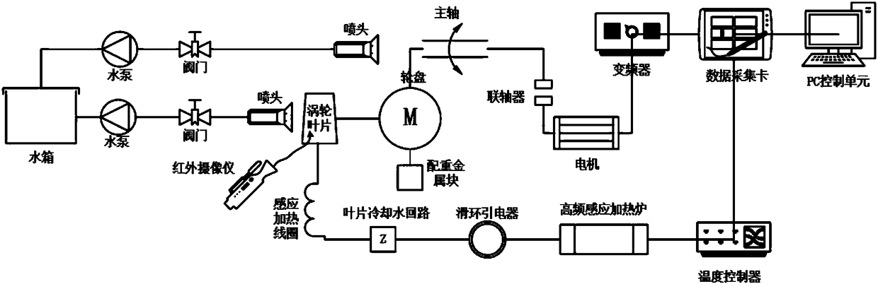
[0033] Such as figure 1 As shown, the turbine blade thermomechanical fatigue test system of this embodiment includes a rotational speed loading device, a temperature loading device, a water cooling system, a data acquisition and control system, and an infrared camera;

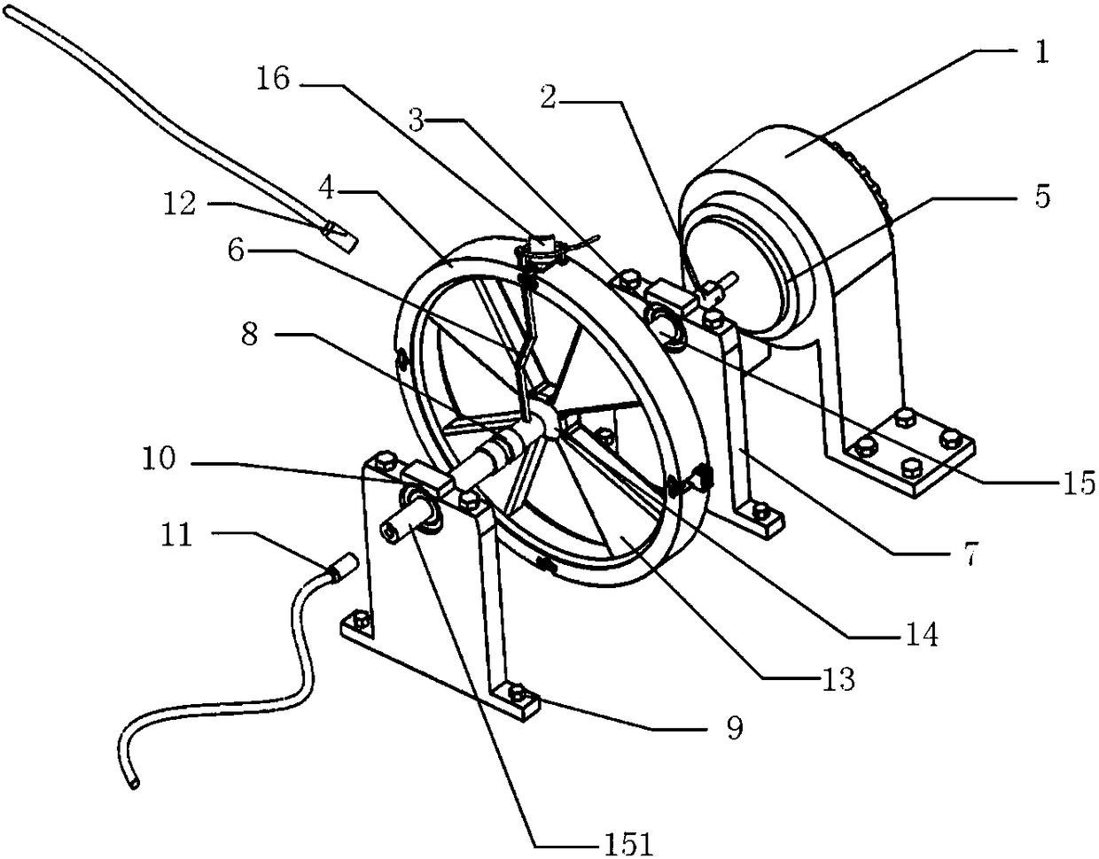
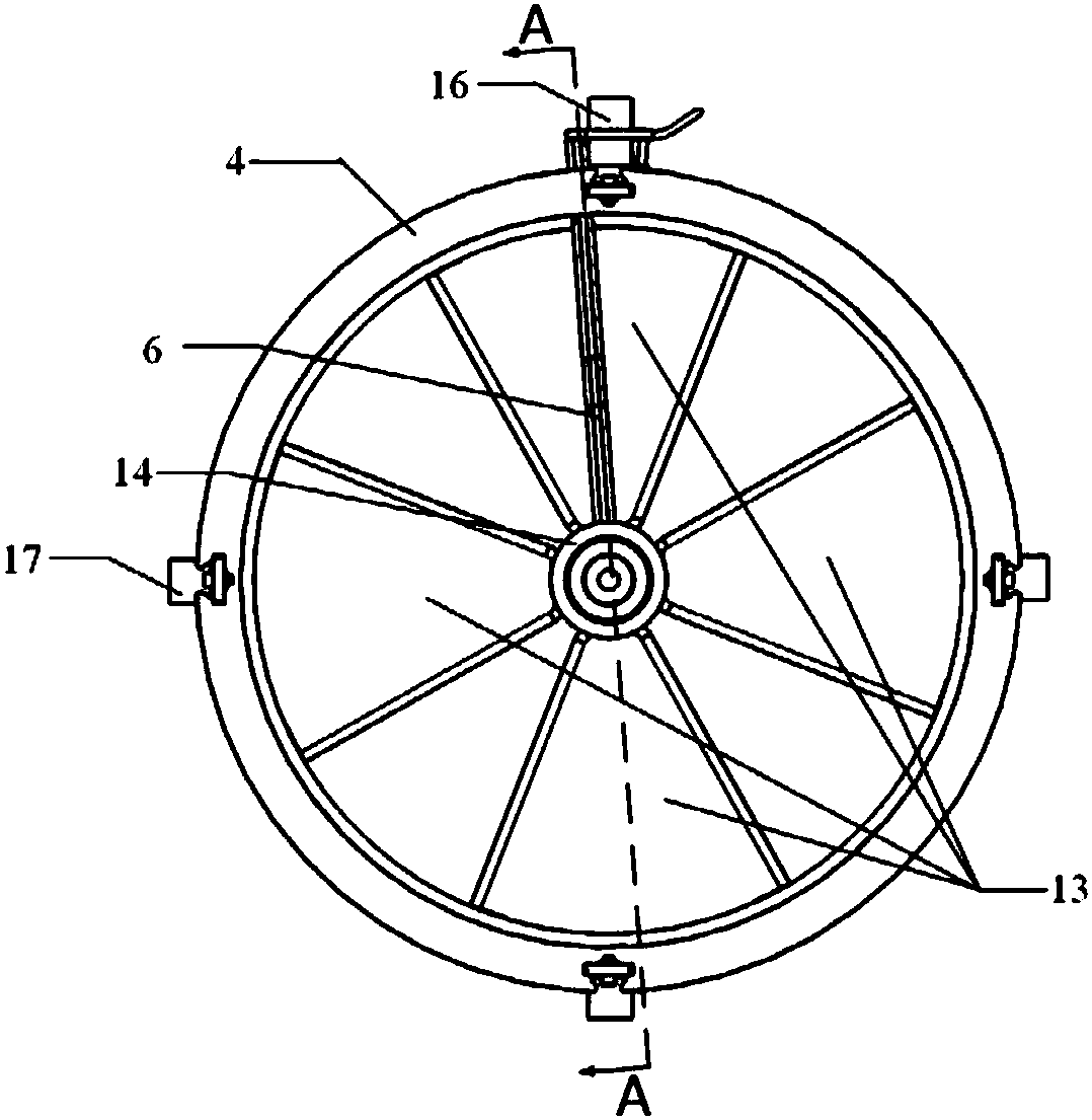
[0034] combine figure 1 , figure 2 , image 3 , Figure 4 , Figure 6 and Figure 7, the speed loading device includes a motor 5 installed on the machine platform (not shown) through a motor support base 1, a main shaft 15 connected to the output shaft of the motor through a coupling 2, and a wheel support 13 and a wheel inside the wheel. The ring 14 is fixedly installed on the wheel disc 4 in the middle of the main shaft; the main shaft is fixedly installed on the machine table through the two front and rear roller bearings 3, the bearing seat 7, the bearing block 10 and the bear...


PUM


Abstract

The invention relates to a turbine blade thermal mechanical fatigue test system. A motor is used for driving a wheel disc capable of installing turbine blades to form a rotating speed loading device.The blades are heated by a round induction heating coil, wherein the round induction heating coil is connected to a high-frequency induction heating furnace and is arranged in the middle of the turbine blade in a sleeved mode. The induction heating coil and the high-frequency induction heating furnace are connected by means of an insulating copper wire passing through a double-channel copper pipeand a slip ring electricity guide and to form a current loop. The centrifugal force generated by the high-speed rotation of the wheel disc is used for providing power for the cooling water circulation, so that the technical problems that heat source is loaded on the turbine blade, and the induction heating coil running at a high speed can be timely cooled are solved. The centrifugal force load andthe cross section working temperature field of the turbine blade in the working environment can be more truly simulated, so that the aero-engine turbine blade thermal mechanical fatigue test result is more accurate and reliable compared with the prior art.

Description

technical field [0001] The invention relates to an aero-engine, in particular to a test system for thermo-mechanical fatigue test of an aero-engine turbine blade. Background technique [0002] The thermomechanical fatigue (TMF) failure of aeroengine turbine blades is the most important failure type during aeroengine service, which seriously affects the safety and reliability of aeroengine operation. The thermomechanical fatigue resistance and service life of aeroengine turbine blades are tested through thermomechanical fatigue tests, and improving the blades according to the test results is an important task in the design of aeroengine turbine blades. [0003] Existing thermomechanical fatigue test methods for superalloy turbine blades mostly use gas thermal shock or high-frequency electric heating on the blade, and at the same time use a fatigue testing machine to clamp the blade to simulate the centrifugal force load on the blade for thermomechanical fatigue test. However...

Claims


Application Information

Patent Timeline
IPC IPC(8): G01M13/00G01M15/02G01M15/14
Inventor 艾延廷关鹏田晶王志张凤玲彭大为
Owner SHENYANG AEROSPACE UNIVERSITY
Why Eureka
Try Eureka