Mobile electronic device and method therein

A mobile electronic equipment, motion technology, applied in the direction of motor vehicles, non-electric variable control, two-dimensional position/channel control, etc. Efficiency, the effect of reducing workload

Pending Publication Date: 2018-08-28
VESTORCH TECH LTD
View PDF0 Cites 11 Cited by
  • Summary
  • Abstract
  • Description
  • Claims
  • Application Information

AI Technical Summary

Problems solved by technology

[0003] The mobile electronic device system described in the embodiments of the present invention, such as a robot system, uses a depth camera, such as an RGB-D camera, to draw indoor maps, realize optimal path planning and more accurate positioning, and solve the problem of traditional sweeping robot mapping and positioning imprecise question

Method used


Image

  • Mobile electronic device and method therein
  • Mobile electronic device and method therein
  • Mobile electronic device and method therein

Examples


Embodiment 1

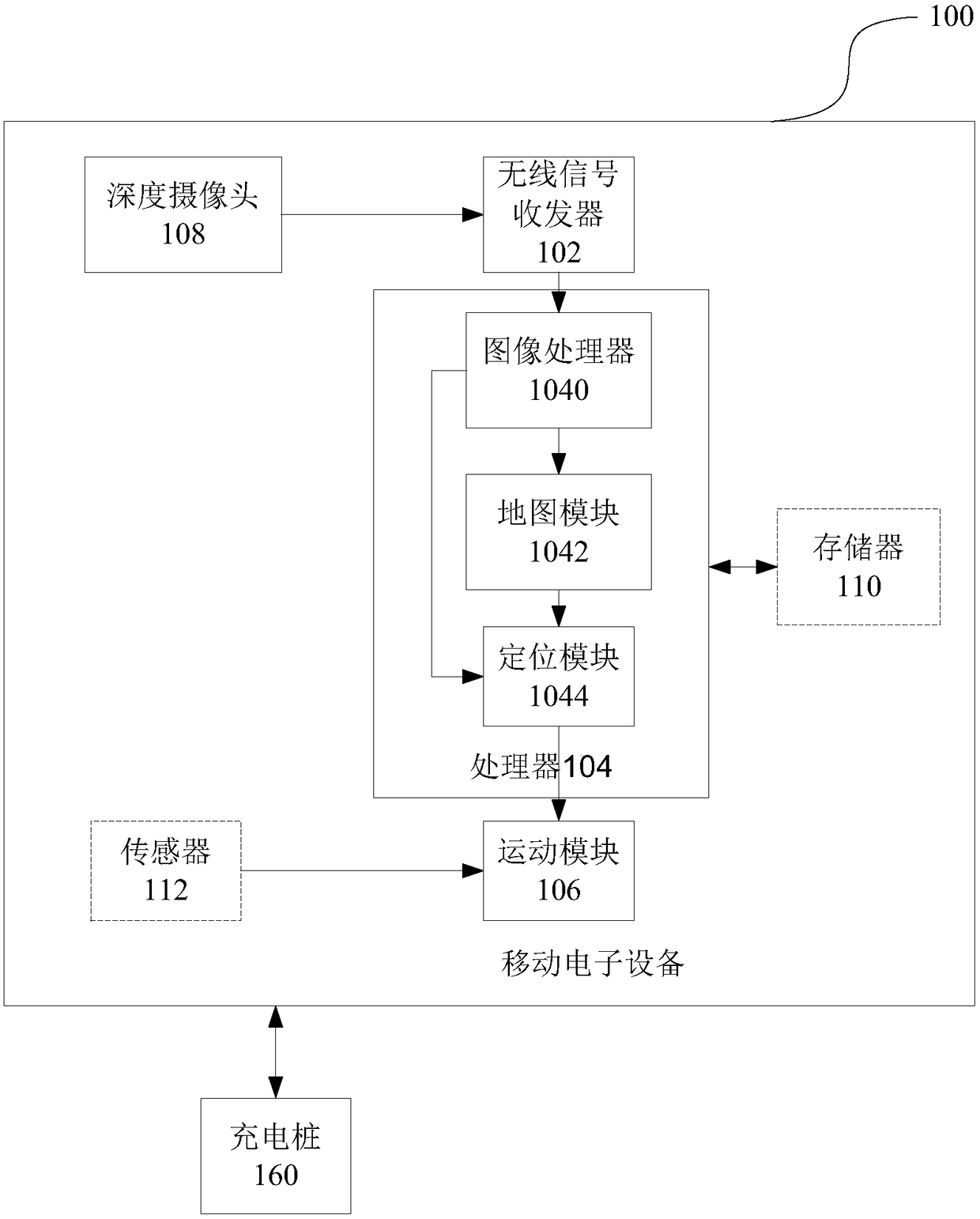
[0013] figure 1 A schematic diagram of a mobile electronic device 100 according to an embodiment of the present invention is shown.

[0014] refer to figure 1 , the mobile electronic device 100 includes but is not limited to sweeping robots, industrial automation robots, service robots, disaster relief robots, underwater robots, space robots, drones, and self-driving cars.

[0015] The signal transmission mode between the mobile electronic device 100 and the charging pile 160 includes but not limited to: Bluetooth, WIFI, ZigBee, infrared, ultrasonic, UWB, etc. In this embodiment, the signal transmission mode is WIFI as an example for description.

[0016] Optionally, the system of the embodiment also includes a second mobile electronic device, such as a mobile APP, communicating with the wireless signal transceiver 102 of the first mobile electronic device 100, and the second mobile electronic device can visually display the 3D modeling information, and user-friendly operati...

Embodiment 2

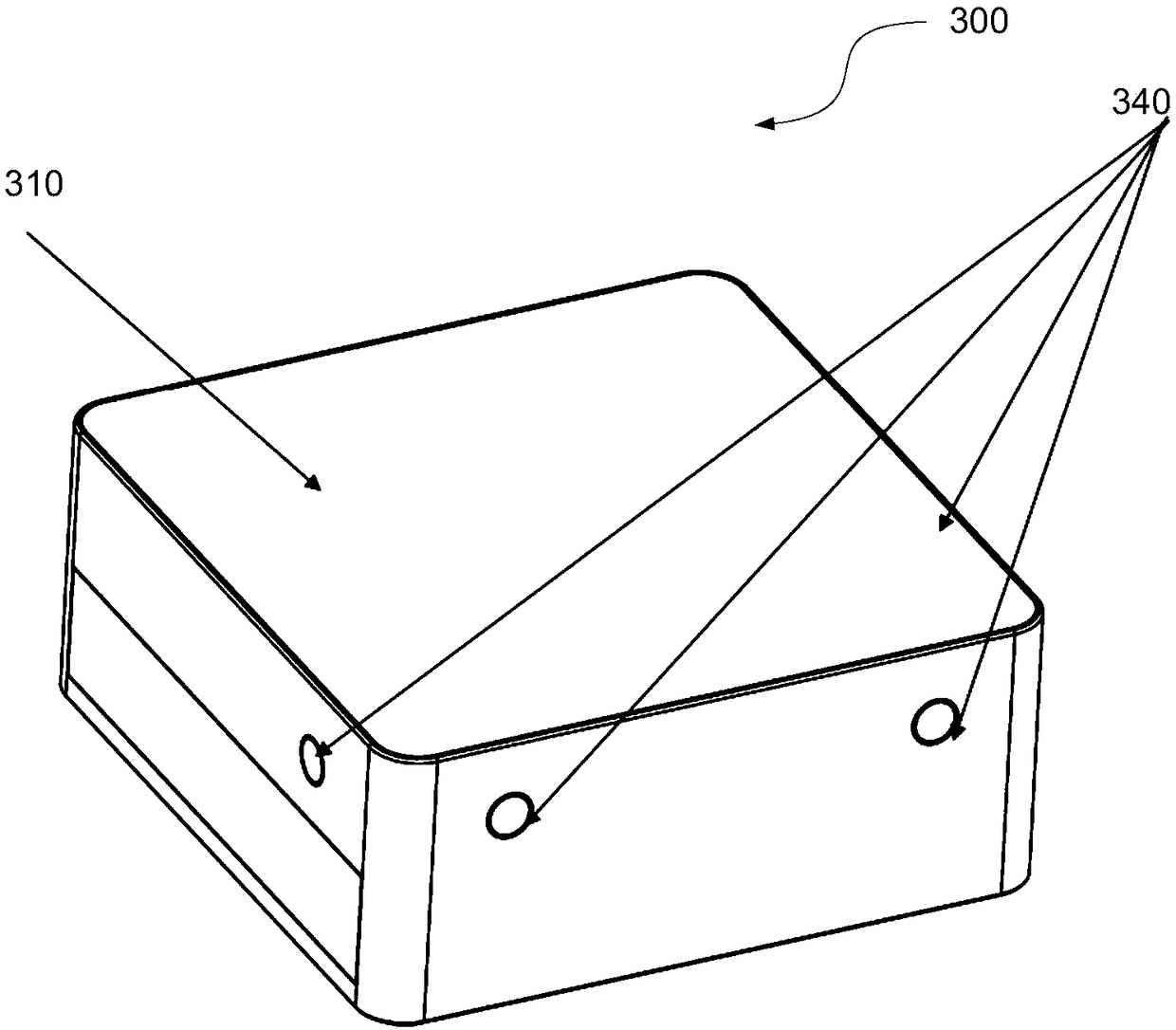
[0035] Figure 3A-3D A schematic diagram of a mobile electronic device 100 according to an embodiment of the present invention is shown. In the following, the mobile electronic device 100 is the robot 300 as an example for description.

[0036] refer to Figure 3A-3D , the robot 300 is mainly composed of five parts: a main body 310 , a wireless transceiver 320 , a microprocessor 330 , a sensor 340 , and a charging pile 350 . The user can use the wireless transceiver 320 , the microprocessor 330 and the charging pile 350 to realize the fixed-point function in a certain area, and use the sensor 340 to assist the main body 310 to complete the designated function operation.

[0037] refer to Figure 3A and Figure 3B The main body 310 is the carrier of the microprocessor 330 and the sensor 340, and the microprocessor 330 can assist the control unit of the main body 310 to perform functions such as movement.

[0038] refer to Figure 3C and Figure 3D , the wireless transcei...

Embodiment 3

[0043] Figure 4 A method 400 in a mobile electronic device is shown, the mobile electronic device 100 includes at least one depth camera 108, a wireless signal transceiver 102, an image processor 1040, a map module 1042, a positioning module 1044 and a motion module 106, wherein the method 400 includes: in block 410, through the wireless signal transceiver 102 communicably connected to the at least one depth camera 108, acquire the plane graphic information collected by the at least one depth camera 108 and the distance information of the objects in the graphic, and The three-dimensional information including planar graphics information and distance information is sent to the image processor 1040; in block 420, the received multiple three-dimensional information is processed through the image processor 1040 communicably connected to the wireless signal transceiver 102; In 430, through the map module 1042 communicably connected to the image processor 1040, according to the plu...


PUM


Abstract

A mobile electronic device comprises at least one depth camera, a wireless signal transceiver, an image processor, a map module, a positioning module and a movement module. The wireless signal transceiver is configured to obtain plane graphic information and distance information of an object in the graph collected by the at least one depth camera while the mobile electronic device moves, and sendmultiple three-dimensional information comprising the plane graphic information and the distance information to the image processor; the image processor is configured to process the received multiplethree-dimensional information; the map module is configured to obtain a task area map by drawing a three-dimensional task area image according to the multiple three-dimensional information obtained after processing of the image processor; the positioning module is configured to record the distance between the current position of the mobile electronic device and a coordinate origin in the task areamap; and the movement module is configured to plan a path according to the task area map and move according to the path.

Description

technical field [0001] The invention relates to the field of electronic equipment. Specifically, the present invention relates to the field of intelligent robotic systems. Background technique [0002] The traditional sweeping robot locates and moves autonomously according to the scanned map, or walks randomly when it collides and rebounds, and cleans the ground at the same time. Therefore, due to immature or inaccurate mapping and positioning technology, traditional sweeping robots cannot fully judge the complex conditions of the ground during the work process, and are prone to lose their position and direction. In addition, because some models do not have positioning capabilities, they can only change direction through the physical principle of collision and rebound, which may even cause damage to household items or the robot itself or even personal injury, causing interference to users and other problems. Contents of the invention [0003] The mobile electronic device...

Claims


Application Information

Patent Timeline
Patent Type & Authority Applications(China)
IPC IPC(8): G05D1/02
CPCG05D1/0225G05D1/0236G05D1/024G05D1/0242G05D1/0251G05D1/0255G05D1/028G05D1/0285G05D2201/0212
Inventor 潘景良陈灼李腾陈嘉宏高鲁
Owner VESTORCH TECH LTD
Why Eureka
Try Eureka