
Hydraulic retarder and auxiliary deceleration system for medium and small vehicles

A technology of hydraulic retarder and deceleration system, applied in the field of automobile brake system, can solve the problems of inability to install hydraulic retarder and large volume, and achieve the effects of light weight, small equipment volume and large damping force

Active Publication Date: 2020-02-18
郑益丽
View PDF7 Cites 0 Cited by
  • Summary
  • Abstract
  • Description
  • Claims
  • Application Information

AI Technical Summary

Problems solved by technology

[0003] However, it is not difficult to see that the impeller, the working chamber where the impeller is located, and the oil storage tank need to be installed separately, so the equipment is relatively large and can only be applied to large vehicles, but it is obviously impossible to install it in a limited installation space for small and medium-sized vehicles. This prior art hydraulic retarder, so the industry is in urgent need of an auxiliary deceleration system suitable for small and medium-sized vehicles

Method used


Image

  • Hydraulic retarder and auxiliary deceleration system for medium and small vehicles
  • Hydraulic retarder and auxiliary deceleration system for medium and small vehicles
  • Hydraulic retarder and auxiliary deceleration system for medium and small vehicles

Examples


Embodiment 1

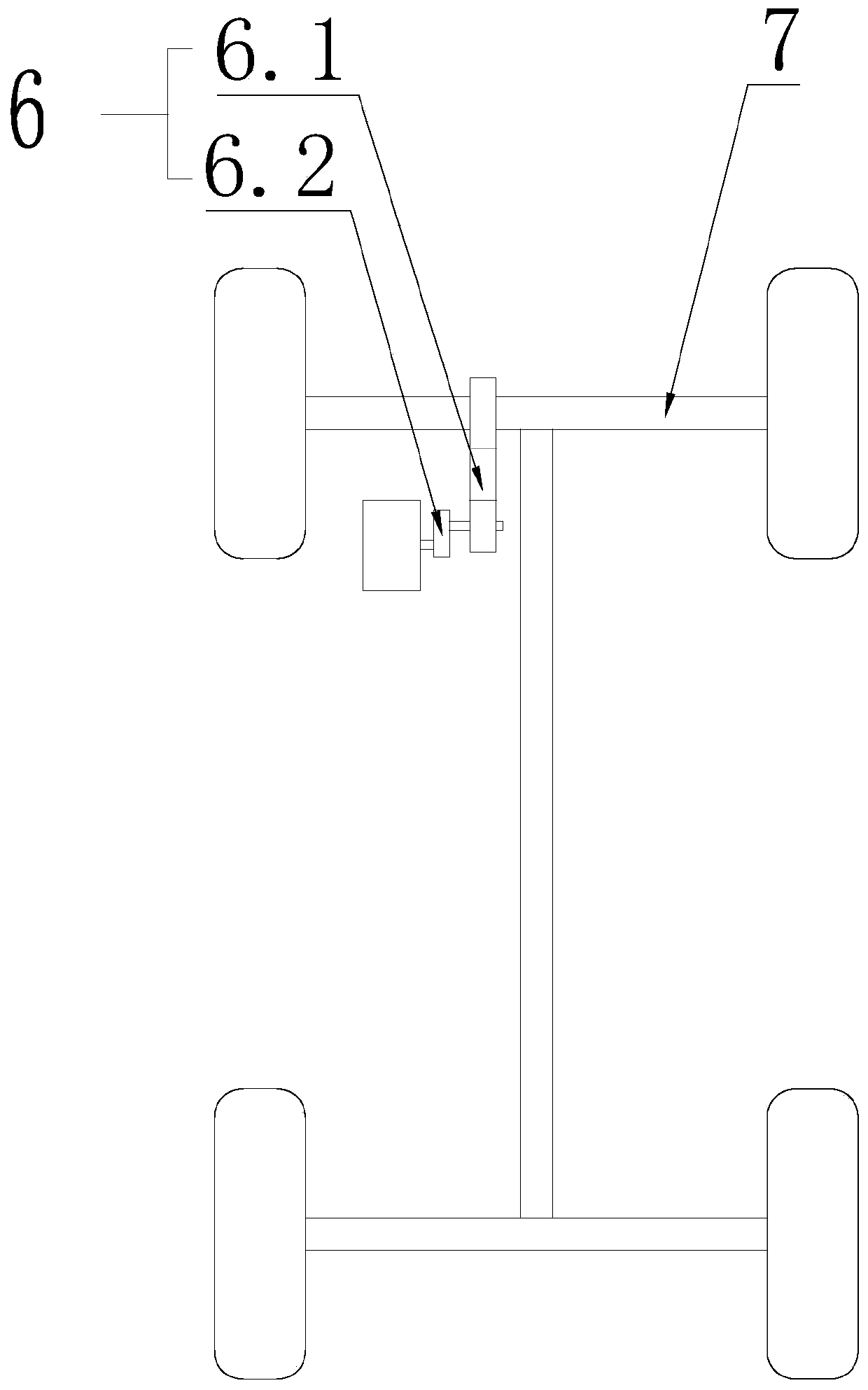
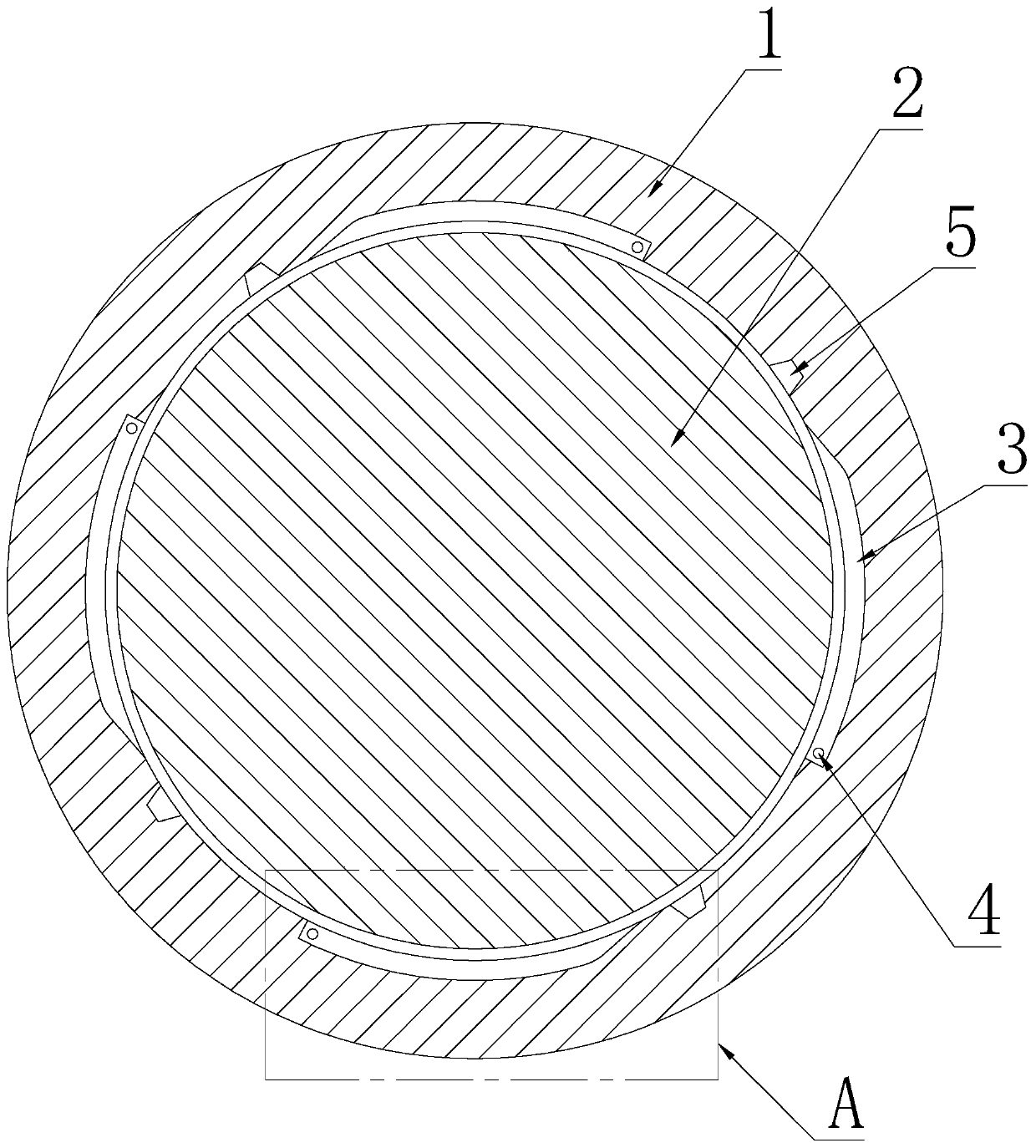
[0035] The invention provides an auxiliary deceleration system comprising such as figure 1 Shown gearbox 6, oil supply system and above-mentioned hydraulic retarder, described stator 1 is fixed on the vehicle frame, and described rotor 2 is connected with transmission shaft 7 of automobile through gearbox 6, and described hydraulic retarder The oil return tank 5 of the force retarder communicates with the input end of the oil supply system, and the oil supply channel 4 of the hydraulic retarder communicates with the output end of the oil supply system. The above-mentioned stator 1 and rotor 2 are accommodated in a casing, and the casing is fixedly installed on the vehicle frame or chassis.

[0036] The gearbox 6 includes a plurality of transmission gear sets, the input gear is called the driving wheel at the beginning, and the output gear is called the end driven wheel. The input shaft and the output shaft of the gearbox 6 are fixedly connected with the drive shaft 7 and the r...

Embodiment 2

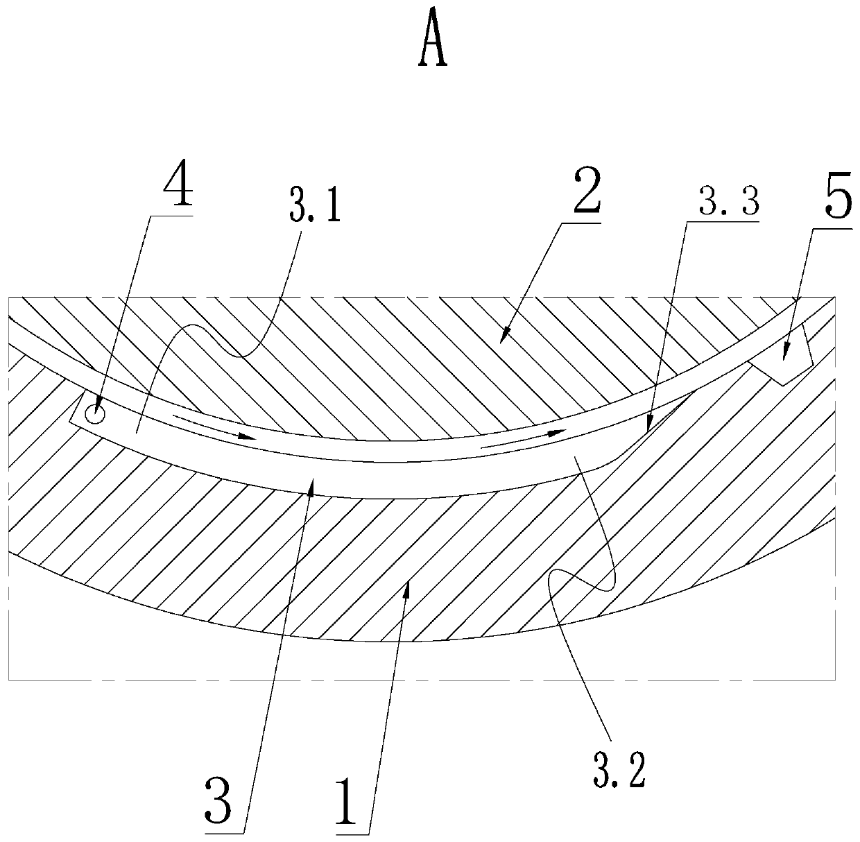
[0042] Such as Figure 4 As shown, the oil supply system includes an oil pump 8, the output end of the oil pump 8 communicates with the oil supply channel 4 on the hydraulic retarder, and the input end of the oil pump 8 communicates with the oil return tank 5 through the oil tank. The oil pump 8, The oil tank and the working oil chamber 3 are sequentially connected through a number of oil pipes 9 to form a circulating oil circuit for circulating oil supply. Increase the oil inlet pressure through the oil pump 8 to avoid a large degree of pressure relief due to the setting of the oil supply channel 4 in the low pressure area, which will affect the pressure maintenance of the oil in the high pressure area 3.2.

[0043] The output end of the above-mentioned oil pump 8 communicates with the oil supply passage 4 on the hydraulic retarder through an oil pipe 9, the input end of the oil pump 8 communicates with the oil outlet of the oil tank through an oil pipe 9, and the oil inlet o...

Embodiment 3

[0066]The gearbox 6 includes a main gearbox 6.1 and a continuously variable transmission 6.2. The input end of the main gearbox 6.1 is connected or disconnected from the drive shaft 7 through a clutch, and the output end of the main gearbox 6.1 is connected to the hydraulic slowdown through the continuously variable transmission 6.2. The rotor 2 of the transmission is connected, and the electronic control module for electrically connecting with the vehicle central control system is provided on the continuously variable transmission 6.2.

[0067] As one of the examples of the third embodiment, the main gearbox 6.1 is used to convert the different speeds of the transmission shaft 7 of the vehicle into a constant speed, and the continuously variable transmission 6.2 converts the constant speed transmitted by the main gearbox 6.1 Adjustment, so as to adjust the load force on the rotor, and finally adjust the damping force applied by the working oil chamber 3 on the rotor 2 to cope ...


PUM


Abstract

The invention discloses a hydraulic retarder for small and medium-sized vehicles. The hydraulic retarder for the small and medium-sized vehicles comprises a stator and a rotor; a stator cavity is formed in the stator; the inner side wall of the stator cavity is provided with at least two work oil grooves; work oil cavities are defined by the outer side wall of the rotor and the work oil grooves; each work oil cavity is sequentially divided into a low pressure area and a high pressure area in the rotating direction of the rotor; oil liquid is arranged in the work oil cavities; the oil liquid isadsorbed to the outer side wall of the rotor by being close to the surface layer of the rotor; the rotor drives the oil liquid in the work oil cavities to flow in the circumferential direction of therotor so that the pressure of oil liquid in the high pressure areas can be larger than that of oil liquid in the low pressure areas; the stator is provided with oil supplying channels communicating with the low pressure areas of the work oil cavities; and the inner side wall of the stator is provided with an oil returning groove. The hydraulic retarder for the small and medium-sized vehicles is small in volume, and therefore the hydraulic retarder is applicable to the small and medium-sized vehicles; and the damping force is large, and therefore the hydraulic retarder for the small and medium-sized vehicles can be used under the steep gradient condition.

Description

technical field [0001] The invention relates to the technical field of automobile brake systems, in particular to a hydraulic retarder and an auxiliary deceleration system for small and medium-sized vehicles. Background technique [0002] The auxiliary deceleration system is one of the products of the development of vehicle safety systems. Its main application environment is to provide a certain damping force for the vehicle during the downhill process, thereby reducing the acceleration of the vehicle without power. The beneficial effect is that the vehicle reduces or does not use the vehicle's own braking system during the long-distance downhill process. Therefore, it reduces the performance of the brake pads due to the continuous friction of the brake pads and even loses the braking effect. The service life of the brake system is increased, and safety guarantee is provided for the long-distance downhill of the vehicle. For example, the hydraulic retarder developed by Voit...

Claims


Application Information

Patent Timeline
Patent Type & Authority Patents(China)
IPC IPC(8): F16D57/02F16D65/78B60K17/08B60T10/02
CPCB60K17/08B60T10/02F16D57/02F16D65/78F16D2065/783F16D2065/787F16D2065/788
Inventor 韩赛
Owner 郑益丽
Learn More