
Control system capable of automatically controlling torque in taking out of minimally invasive hollow nail

A technology of control system and hollow nail, which is applied in the medical field and can solve the problems of poor applicability, intuition, and low accuracy of measurement results.

Inactive Publication Date: 2018-08-31
LUOYANG ORTHOPEDIC TRAUMATOLOGICAL HOSPITAL
View PDF5 Cites 1 Cited by
  • Summary
  • Abstract
  • Description
  • Claims
  • Application Information

AI Technical Summary

Problems solved by technology

[0007] The existing minimally invasive hollow nail removal process is not intuitive enough to observe the position of the hollow nail through a plane image; at the same time, the position of the hollow nail is drawn by a brush, and the positioning is not accurate enough
[0008] The existing phase noise measurement method uses the frequency response of the phase extraction circuit, which has the problem of low accuracy of the measurement results
Poor application in clinical medicine

Method used


Image

  • Control system capable of automatically controlling torque in taking out of minimally invasive hollow nail
  • Control system capable of automatically controlling torque in taking out of minimally invasive hollow nail
  • Control system capable of automatically controlling torque in taking out of minimally invasive hollow nail

Examples


Embodiment 1

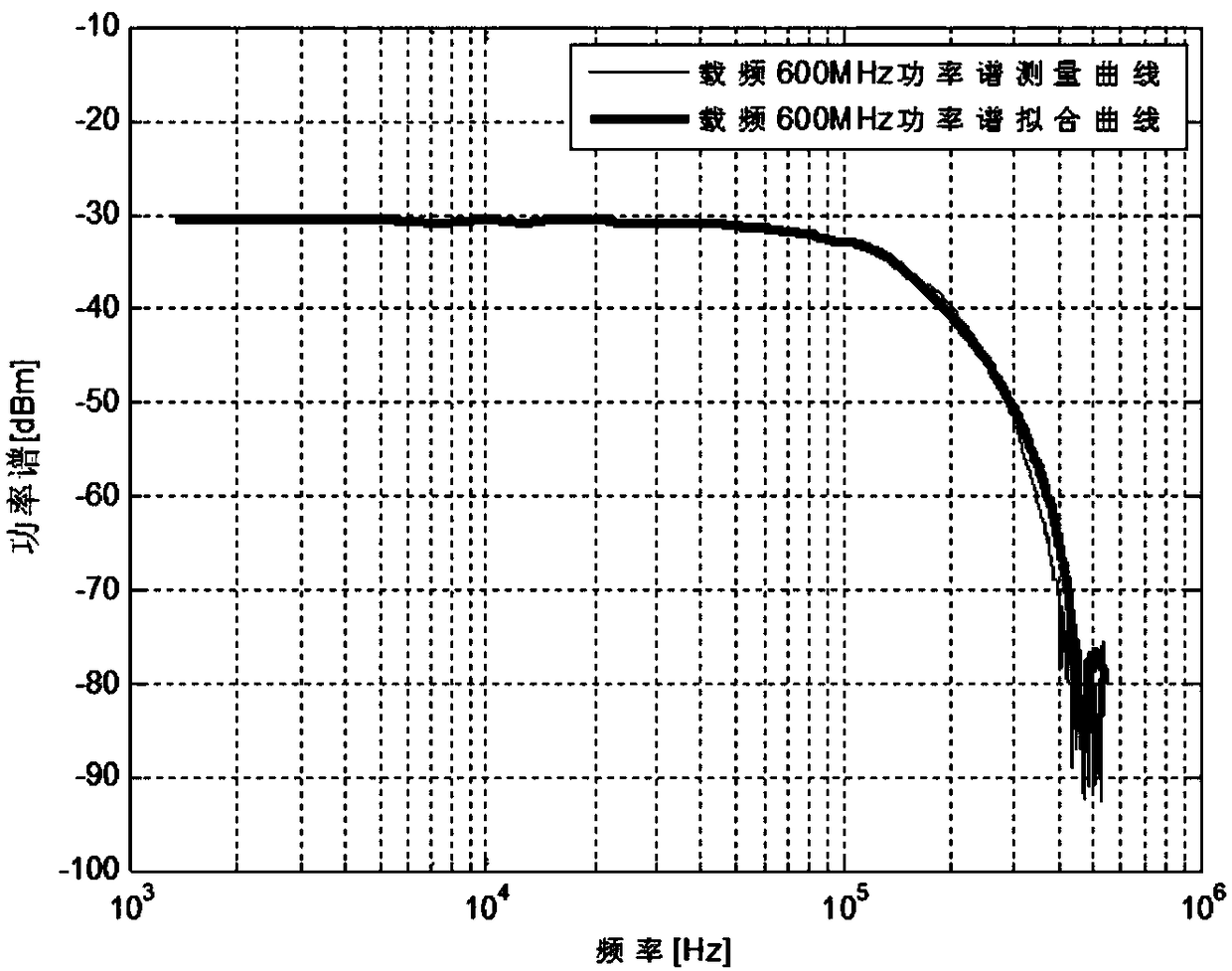
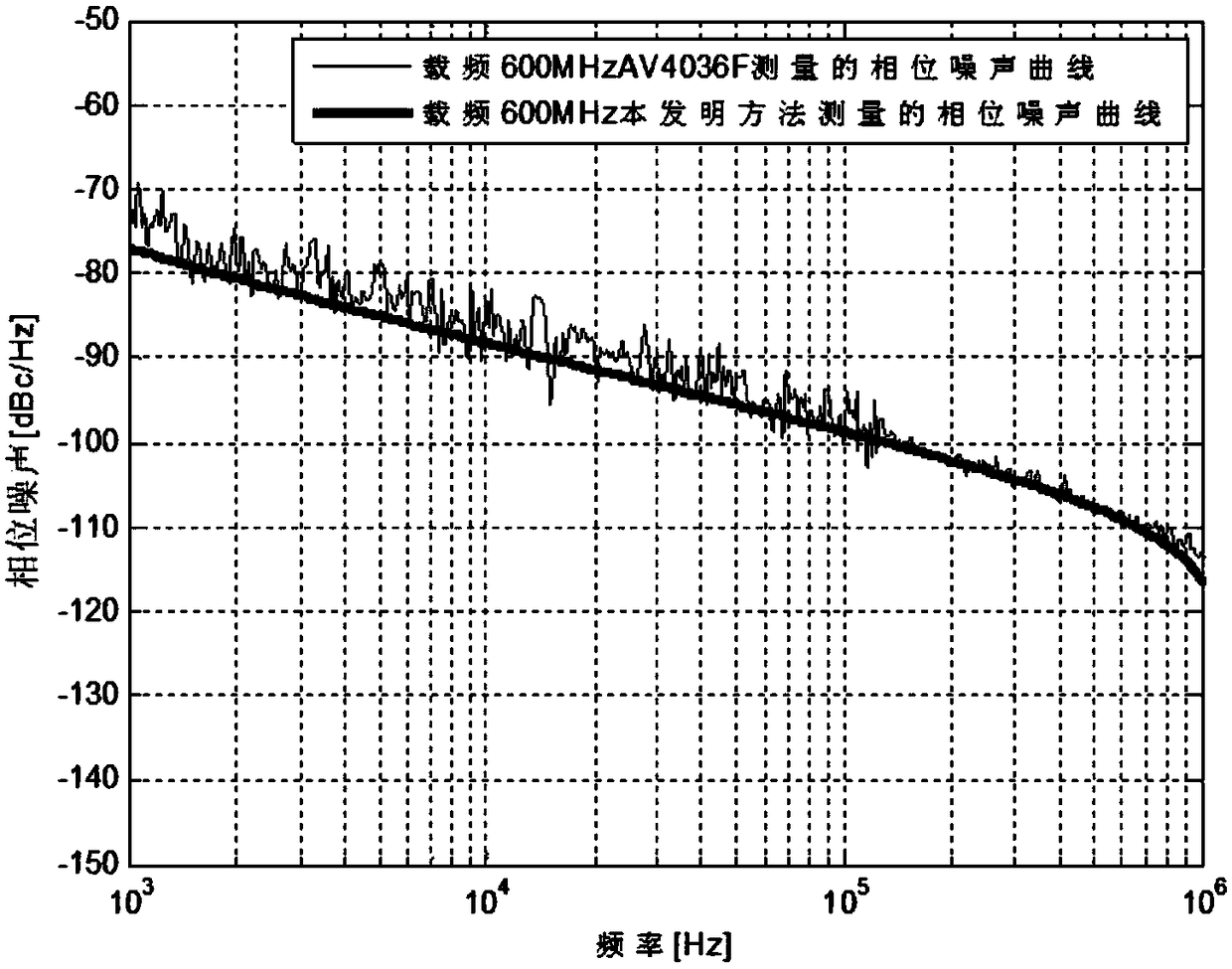
[0135] In this embodiment, the carrier frequency of the signal under test is 600MHz, the power spectrum of the signal under test is measured by a spectrum analyzer AV4036F, and the phase noise of the signal under test is calculated by using the measured power spectrum data according to the method of the present invention, and the phase noise of the phase noise is given. measurement results. The phase noise measurement results of the algorithm of the present invention are compared with the results directly measured by the phase noise measurement module of AV4036F to illustrate the implementation process and effectiveness of the method of the present invention.

[0136] figure 2 The power spectrum curve of the measured signal measured by the spectrum analyzer AV4036F and the fitting result of nonlinear least square method using the power spectrum measurement data are given. The phase noise coefficient of the measured signal obtained from the fitting result is:

[0137]

[...

Embodiment 2

[0146] In the embodiment, the carrier frequency of the measured signal is 800MHz. Use the spectrum analyzer AV4036F to measure the power spectrum of the signal under test, use the measured power spectrum data to calculate the phase noise of the signal under test according to the method of the present invention, and give the measurement result of the phase noise. The phase noise measurement results of the algorithm of the present invention are compared with the results directly measured by the phase noise measurement module of AV4036F to illustrate the implementation process and effectiveness of the method of the present invention.

[0147] Figure 4 The power spectrum curve of the measured signal measured by the spectrum analyzer AV4036F and the fitting result of nonlinear least square method using the power spectrum measurement data are given. The phase noise coefficient of the measured signal obtained from the fitting result is:

[0148]

[0149]

[0150]

[0151]...


PUM


Abstract

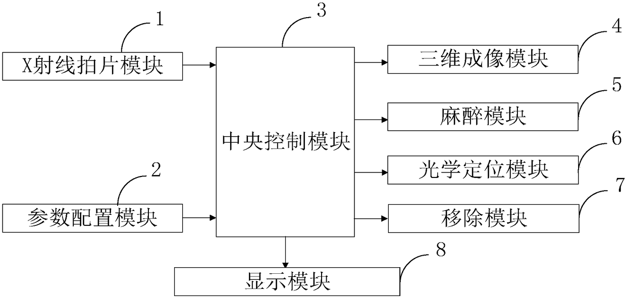
The invention belongs to the field of medical technology and discloses a control system capable of automatically controlling torque in taking out of a minimally invasive hollow nail. The control system comprises an X-ray shooting module, a parameter setting module, a center control module, a three-dimensional imaging device, an anesthesia module, an optical positioning module, a removing module and a displaying module. According to the invention, through the three-dimensional imaging module, an X-ray shooting image before an operation of a patient is read and a three-dimensional stereo image is generated, so the position of the hollow nail can be directly observed; meanwhile, through the optical positioning module, an optical tracking mark on a minimally invasive surgery device is capturedso that the space position of the hollow nail in the body of the patient is figured out in a quite precise manner, so the removing accuracy of the hollow nail is improved; and all the modules work under control of the center control module.

Description

technical field [0001] The invention belongs to the field of medical technology, and in particular relates to a control system for taking out a minimally invasive hollow nail with automatic torque control. Background technique [0002] At present, the existing technologies commonly used in the industry are as follows: [0003] Minimally invasive is a technology that only causes minor trauma to the patient during the surgical treatment and leaves only minor wounds after surgery. It is a scientific and technological achievement compared to traditional surgery. Therefore, minimally invasive is a word specially connected with surgery and surgery, such as minimally invasive surgery, minimally invasive surgery, etc. However, in the existing minimally invasive hollow nail removal process, the position of the hollow nail is observed through a plane image, which is not intuitive; at the same time, the position of the hollow nail is drawn with a brush, and the positioning is not acc...

Claims


Application Information

Patent Timeline
Patent Type & Authority Applications(China)
IPC IPC(8): G16H40/63A61B34/20A61B17/92G05D17/02
CPCA61B17/92A61B34/20A61B2034/2055A61B2034/2065G05D17/02G16H40/63
Inventor 马文龙赵熙熹陈洪干陈柯
Owner LUOYANG ORTHOPEDIC TRAUMATOLOGICAL HOSPITAL
Learn More