Circular tool for cutting material

A technology for cutting materials and tools, which is used in the manufacture of tools, tools for sawing machines, and tool manufacturing for sawing machines. The effect of short durability and reduced cutting speed

Inactive Publication Date: 2018-08-31
JULIA UTENSILI
View PDF8 Cites 0 Cited by
  • Summary
  • Abstract
  • Description
  • Claims
  • Application Information

AI Technical Summary

Problems solved by technology

[0018] However, when cutting in extremely hard materials, the cutting stress will very predictably occur causing the braze to yield, rendering the entire round tool completely useless
[0019] Another disadvantage of said solution is that, for each size of said support disc, a predetermined cutting insert having dimensions suitable for subsequent connection to said support disc must be designed and produced
[0020] Another disadvantage of the solution is the complexity of forming the connection between the cutting insert and the support disc

Method used


Image

  • Circular tool for cutting material
  • Circular tool for cutting material
  • Circular tool for cutting material

Examples


Embodiment Construction

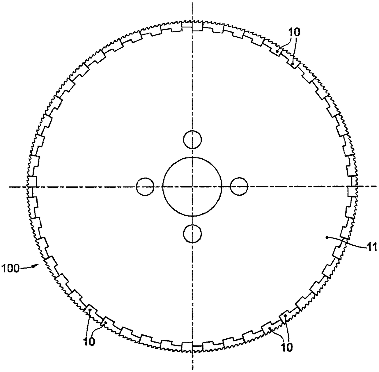
[0057] According to the present description and with reference to the accompanying drawings, the present invention relates to a circular tool 100 for cutting metallic material such as low or high alloy steel, titanium, aluminum or the like.

[0058] Furthermore, the tool 100 is particularly suitable for cutting small workpieces with reduced thickness.

[0059] For example, the tool 100 can cut solid rods with diameters between 5 mm and 120 mm, pipes with dimensions smaller than 5 mm and larger than 600 mm and thicknesses between 0.4 mm and 25 mm, or through Parallelepiped workpieces obtained by forming round tubes. Furthermore, the tool 100 may be adapted to a particular machine, such as an orbital machine, in which the same tool 100 is made to rotate around a workpiece in order to cut larger sized workpieces.

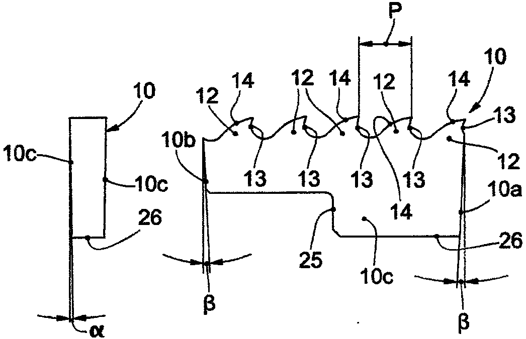
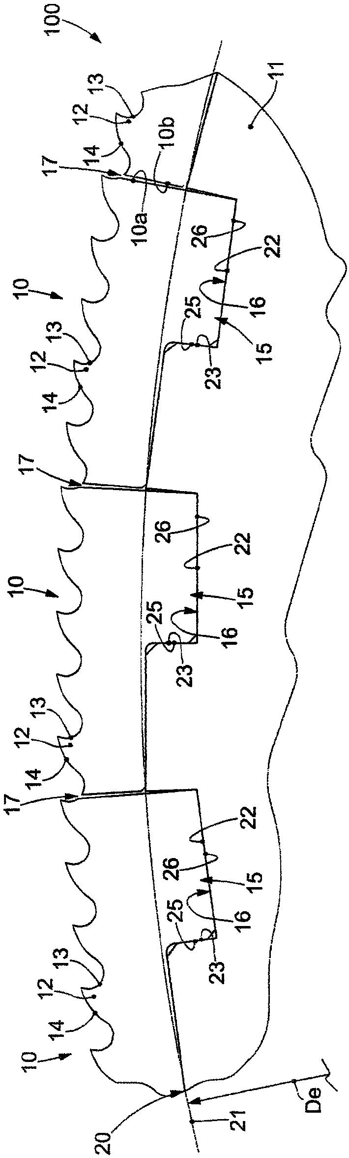
[0060] The tool 100 comprises a support disc 11 and a plurality of cutting inserts 10 attached to the circumferential periphery of the support disc 11 .

[0061] The...


PUM


Abstract

Circular tool for cutting material comprising a support disc (11) and a plurality of cutting inserts (10) attached on the circumferential periphery of the support disc (11).

Description

technical field [0001] The invention relates to a round tool for cutting hard materials, such as steel or the like. [0002] The tool may be mounted on a machine in which mutual advancement of the tool and the material to be cut takes place by either the tool or the material to be cut. Background technique [0003] In recent years, in all fields, especially in the field of automation, there has been an increasing demand for the use of circular saws with ever-increasing thickness. Due to the generation of chips, this saw reduces work scraps. [0004] In recent years, new steels have been developed, also called high resistance steels, which have extremely high mechanical hardness properties and mechanical resistance, and are used in the manufacture of products such as pipes and profiles, which are subsequently used in various A shape area. These types of materials offer the same strength and safety as materials used just a few years ago, with fewer wear-resistant parts and ...

Claims


Application Information

Patent Timeline
Patent Type & Authority Applications(China)
IPC IPC(8): B23D61/02
CPCB23D61/023B23D61/021B23D61/025B23D65/00
Inventor 特里斯塔诺·恰尼米歇尔·皮龙蒂
Owner JULIA UTENSILI
Why Eureka
Try Eureka