Compression device and separation method for controlling mass flow

A technology for controlling quality and mass flow, which is applied in the field of refrigerant devices, and can solve problems such as lowering of refrigerant density, higher temperature of hot gas, and lower volumetric efficiency of compressors.

Active Publication Date: 2019-12-13
HANON SYST
View PDF8 Cites 0 Cited by
  • Summary
  • Abstract
  • Description
  • Claims
  • Application Information

AI Technical Summary

Problems solved by technology

As the inlet temperature rises, the density of the introduced refrigerant at constant pressure decreases, which also reduces the volumetric efficiency of the overall compressor and results in an increase in the temperature of the hot gas at the outlet of the compressor

Method used


Image

  • Compression device and separation method for controlling mass flow
  • Compression device and separation method for controlling mass flow
  • Compression device and separation method for controlling mass flow

Examples


Embodiment Construction

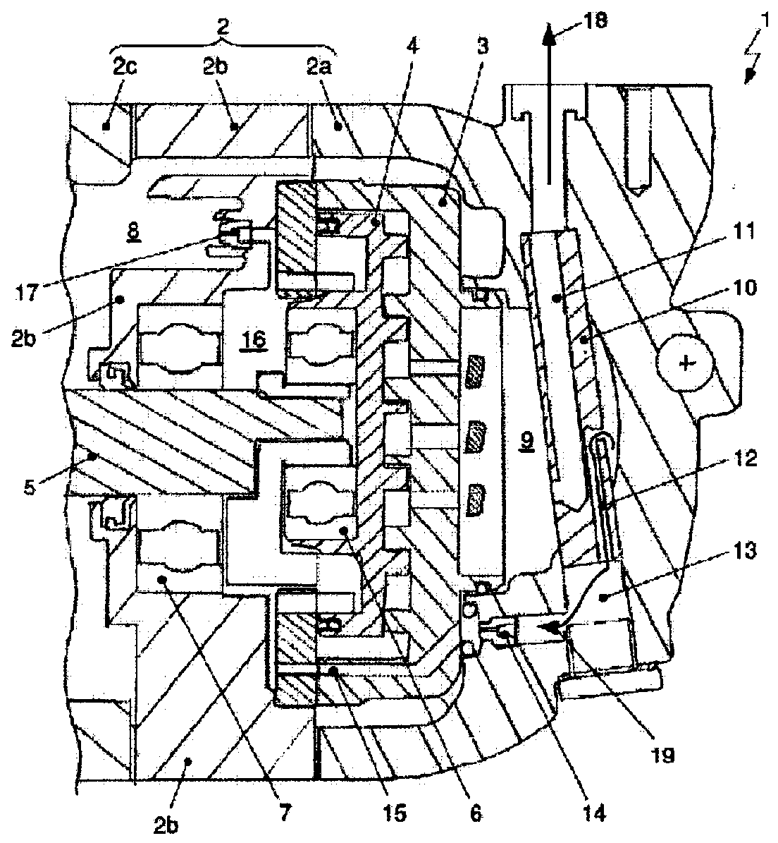
[0050] figure 1 The compressor 1 is shown in cross-section with a structure 10 for separating the mass flow control, also referred to below as separator 10 . In addition, the compressor 1 also includes a compression mechanism for sucking, compressing, and discharging refrigerant as a gaseous fluid including oil as a lubricant for lubrication. The compression mechanism and the separator 10 are arranged inside the housing 2 .

[0051] The compressor 1 is realized as a scroll compressor, wherein a rear housing element 2 a , a middle housing element 2 b and a front housing element 2 c form a housing 2 in the assembled state. The compression mechanism of the compressor 1 includes a stationary stator 3 and a movable orbiter 4 each having a base plate and being formed in a scroll form and extending from the base plate. extended wall. The base plates are arranged relative to each other such that the walls are interlocked. The stationary stator 3 is realized in the housing 2 or as ...


PUM


Abstract

The invention relates to a device (1; 1'; 1") for compressing a gaseous fluid, in particular a refrigerant. The compression device (1; 1'; 1") comprises: a housing (2), the housing has a suction pressure chamber (8) and a high pressure chamber (9); a compression mechanism; and a device (10; 10'; 10") formed in the high pressure chamber (9) to separate control from the fluid / lubricant mixture The mass flow controls the compression mechanism. In order to separate the mass flow as the gaseous fluid controlling the mass flow, the separation device (10; 10'; 10") has a first flow channel (11; 11'; 11") which flows Channels are formed and arranged on the separation device to lead the main mass flow of the compressed fluid / lubricant mixture out of the compression device (1; 1'; 1"), and the separation device (10; 10'; 10") has a first Two flow passages (12; 12'; 12") formed and arranged on the separation device in order to direct the control mass flow from inside the compression device (1; 1'; 1") to the suction pressure chamber (8) ). The present invention also relates to a method for separating and controlling a mass flow using a device (10; 10'; 10") for a device (1; 1'; 1") for compressing a gaseous fluid Internal control mass flow for separation.

Description

technical field [0001] The invention relates to devices for compressing gaseous fluids, especially refrigerants. The device comprises a housing, a compression mechanism and a structure having a suction pressure chamber and a high pressure chamber, the structure being realized in the vicinity of the high pressure chamber for separating the control mass flow from the fluid-lubricant mixture to control the compression mechanism. The invention also relates to a method for separating a control mass flow in a device for compressing a gaseous fluid by means of a structural element for separating the control mass flow. Background technique [0002] Compressors known in the prior art were developed to separate oil from a refrigerant-oil mixture by means of an oil separator, such compressors are used for example in mobile applications, in particular in air-conditioning systems of motor vehicles, for cooling by Refrigerant circulation system to compress and transport refrigerant. In...

Claims


Application Information

Patent Timeline
Patent Type & Authority Patents(China)
IPC IPC(8): F04C18/02F04C29/02F04C29/12
CPCF25B1/04F25B43/02F04C18/0215F04C29/0092F04C29/026F04C29/12F04C18/3443F04C2250/102F04B39/16F04C2/025
Inventor 菲利普·科扎拉罗曼·赫克特
Owner HANON SYST
Why Eureka
Try Eureka