Spring cleaning equipment and spring cleaning process applying same

A technology for cleaning equipment and cleaning tanks, which is applied in the field of spring cleaning technology and spring cleaning equipment, which can solve the problems of shortening the service life of springs, small spring pitch, corrosion, etc., and achieve the effect of prolonging service life and reducing the frequency of replacement

Active Publication Date: 2018-09-04
浙江兰菱机械股份有限公司
View PDF11 Cites 1 Cited by
  • Summary
  • Abstract
  • Description
  • Claims
  • Application Information

AI Technical Summary

Problems solved by technology

[0004] In the above technical solution, after the springs are ultrasonically cleaned, they are dried with a heating dryer. However, in actual use, because some springs have small pitches, it is easy to have moisture in the pitch gaps, which is difficult to remove, and it is easy to cause follow-up problems. Corrosion, shorten the service life of the spring

Method used


Image

  • Spring cleaning equipment and spring cleaning process applying same
  • Spring cleaning equipment and spring cleaning process applying same
  • Spring cleaning equipment and spring cleaning process applying same

Examples


Embodiment 1

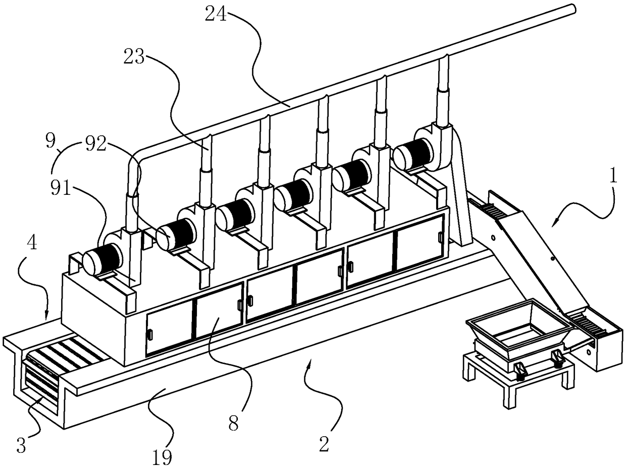
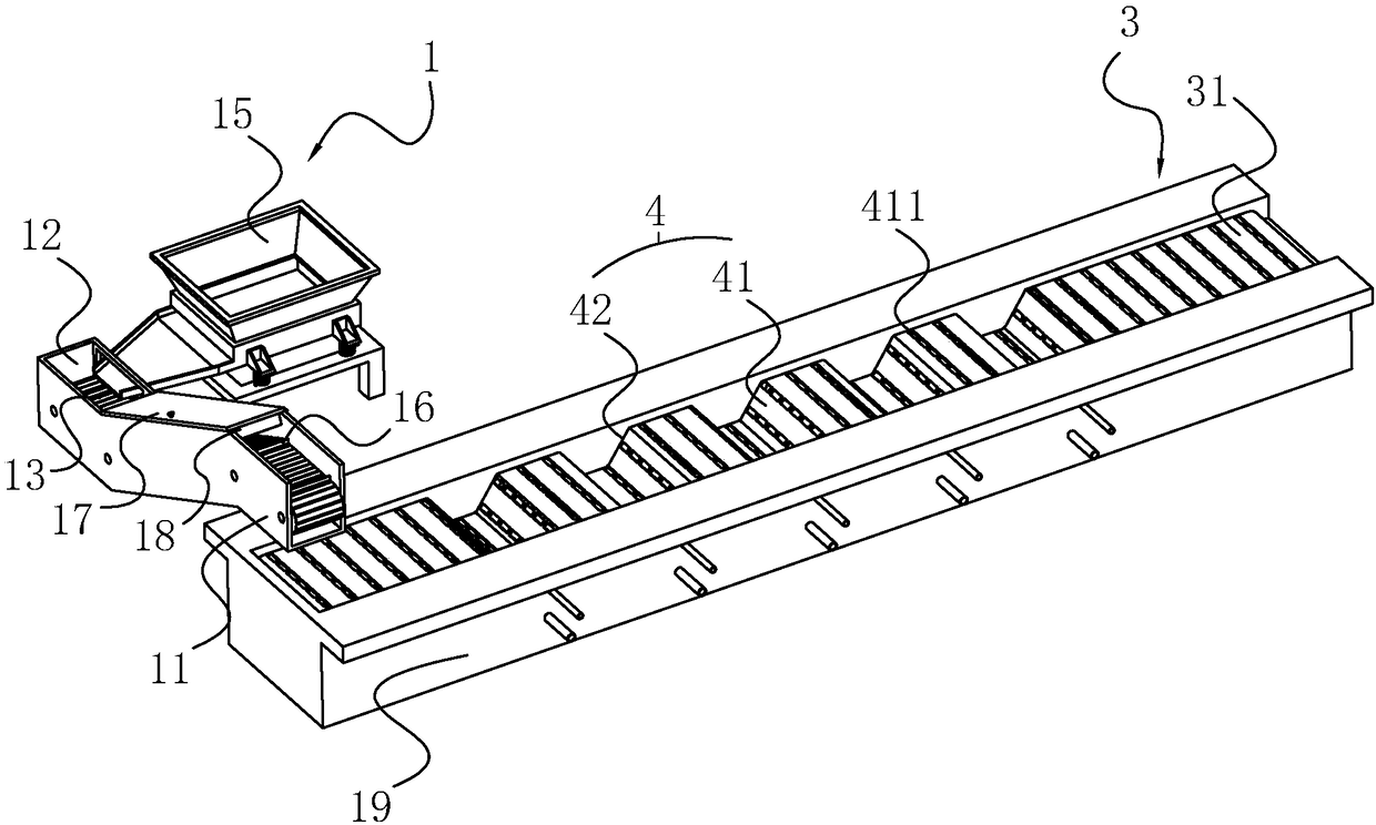
[0046] A spring cleaning equipment, refer to figure 1 As shown, it includes a feeding device 1 for storing a certain amount of springs to be cleaned, a cleaning device for cleaning the springs 2, a feeding device 3 for discharging and unloading the cleaned springs, and a slave cleaning device 2 Extend to the conveying mechanism 4 of the unloading device 3, so that during the cleaning process, the unloading device 3 sends the spring to be cleaned to the conveying mechanism 4, and then the conveying mechanism 4 sequentially passes the springs through the washing device 2, and finally the unloading The device 3 sends out the cleaned spring.

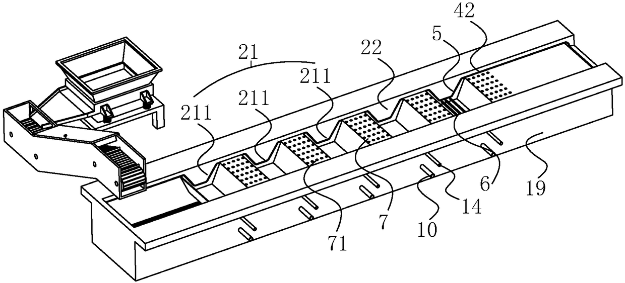
[0047] Reference figure 2 As shown, the cleaning device 2 includes a water washing tank 21 and a dehydration tank 22 arranged in sequence. The water washing tank 21 includes three ultrasonic cleaning tanks 211 arranged in sequence. The ultrasonic cleaning tank 211 is provided with an upper opening, and the bottom of the ultrasonic cleaning tank...

Embodiment 2

[0058] A spring cleaning process, which is characterized in that it includes the following steps:

[0059] Step A: Vibrate to remove solid particles and dust, pour the spring to be cleaned into the vibrating plate to vibrate to remove solid particles and dust;

[0060] Step B: Flatten, use the lifting chain plate 13 to lift the spring that has been vibrated to remove dust, and rely on the scraper 18 to prevent the spring on the lifting chain plate 13 from stacking as much as possible, so that the spring can be laid flat on the conveyor chain plate 41 surface;

[0061] Step C: For the first ultrasonic cleaning, the spring is transported to the first ultrasonic cleaning tank 211 by the conveyor chain 41 for cleaning, and the metal processing part grease cleaner is added to the ultrasonic cleaning tank 211, and the ultrasonic cleaning tank 211 The temperature is maintained at about 50℃;

[0062] Step D: Inhale for the first time, the conveyor chain 41 transports the spring from the firs...


PUM


Abstract

The invention provides spring cleaning equipment and a spring cleaning process applying the same. The spring cleaning equipment comprises a feeding device, a cleaning device, a discharging device anda conveying mechanism which are connected sequentially, wherein the conveying mechanism extends from the cleaning device to the discharging device. The cleaning device comprises a washing tank and dehydration tank which are arranged successively, and dehydration solvents are injected into the dehydration tank. The washing tank comprises a plurality of ultrasonic cleaning tanks which are connectedsequentially. The spring cleaning process comprises the following steps of A, vibration ash removal; B, flattening; C, ultrasonic cleaning for the first time; D, air suction for the first time; E, ultrasonic cleaning for the second time; F, air suction for the second time; G, ultrasonic cleaning for the third time; H, air suction for the third time; I, dehydration; J, rust-proof treatment and K, discharging. According to the spring cleaning equipment and the spring cleaning process applying the same, residual water after spring cleaning can be better removed, the storage time and the service life of springs are prolonged.

Description

Technical field [0001] The invention relates to a spring production process, in particular to a spring cleaning equipment and a spring cleaning process using the equipment. Background technique [0002] A spring is a mechanical part that uses elasticity to work. It is made of elastic material. It deforms under the action of external force and returns to its original state after removing the external force. In order to ensure the performance of the spring, the spring needs to be subjected to stress relief annealing treatment, grinding support formation, shot peening, chamfering, standing treatment and other production processes. These processes will cause the spring to contain particles or dust that affect the cleaning of the spring. . For springs used in oil circuit systems or under precise conditions, the particles or dust attached to the spring must be thoroughly cleaned after the finished product inspection, otherwise it will affect the reliability of the spring and its compo...

Claims


Application Information

Patent Timeline
Patent Type & Authority Applications(China)
IPC IPC(8): B08B7/02B08B3/12B08B13/00F26B5/16B05C3/09B05C13/02B05C11/10
CPCB05C3/09B05C11/1042B05C13/02B08B3/12B08B7/02B08B13/00F26B5/16
Inventor 姜晓炜王永祥程海波
Owner 浙江兰菱机械股份有限公司
Why Eureka
Try Eureka