Cathode for electrolytic machining of small-size inner wall annular groove and using method thereof

A small size, ring groove technology, applied in machining electrodes, electric machining equipment, electrode manufacturing, etc., can solve the problem that the cathode and the inner wall of the workpiece tube are not concentric and different axes, the positioning surface is difficult to maintain in the same horizontal plane, and there is no automatic centering. , positioning function and other issues, to achieve the effect of reducing stray corrosion, simple structure and convenient implementation

Pending Publication Date: 2018-09-04
XIAN TECHNOLOGICAL UNIV
View PDF0 Cites 7 Cited by
  • Summary
  • Abstract
  • Description
  • Claims
  • Application Information

AI Technical Summary

Problems solved by technology

However, the problems of this device are: 1. Since the non-actual working area on the cathode substrate has not been insulated, the influence of stray corrosion on the forming accuracy of the inner wall ring groove has not been considered, which will cause the actual size of the inner wall groove of the circular tube workpiece 2. Because the central axis of the cathode and the central axis of the inner wall of the tube workpiece are difficult to keep on the same axis, and the positioning surface of the tool cathode and the workpiece is difficult to keep on the same horizontal plane, it is easy to cause the cathode and the inner wall of the workpiece tube to be out of center. Coaxial, which has a huge impact on the forming accuracy of the inner wall ring groove; 3. In addition, the device does not have automatic centering and positioning functions

Method used


Image

  • Cathode for electrolytic machining of small-size inner wall annular groove and using method thereof
  • Cathode for electrolytic machining of small-size inner wall annular groove and using method thereof
  • Cathode for electrolytic machining of small-size inner wall annular groove and using method thereof

Examples


Embodiment Construction

[0020] The present invention will be further described below with reference to the accompanying drawings, so as to facilitate the understanding of technical personnel.

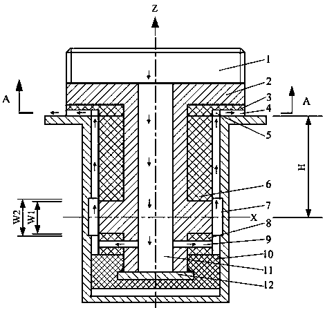
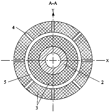
[0021] see Figure 1-Figure 3 , a small-sized inner wall ring groove electrolytic machining cathode, including a conductor 2 with an inverted "soil" cross section and a plug 12, the outer wall of the upper end of the conductor 2 is provided with an external thread 1, and the middle of the conductor 2 is provided There is an annular boss, and the inside of the conductor 2 is a through-hole structure along the axial direction.

[0022] The lower end of the electric body 2 is welded with a plug 12 whose diameter is larger than that of the conductor 2, and the lower end of the conductor 2 and the periphery of the plug 12 are provided with a cover-shaped bottom insulating layer 10, and the ring shape of the bottom insulating layer 10 A lower insulating ring 8 is arranged between the upper end and the conductor 2. ...


PUM


Abstract

The invention relates to a cathode for electrolytic machining of a small-size inner wall annular groove and a using method thereof, and belongs to the field of electrolytic machining and manufacturing. The cathode mainly comprises an external thread joint, a tool cathode base body, a hard insulation layer, a side wall insulation layer, a lubricating insulation layer, a metal plug, a main flow channel and branch flow channels; the interior of the tool cathode base body is of a through hole structure, and the bottom of the base body and the metal plug are welded into a whole; an annular groove structure and circular groove structures uniformly distributed in the circumference are formed in the hard insulation layer so that an electrolyte can be conveniently discharged; and the side wall insulation layer plays a role in reducing stray corrosion. According to the cathode and the using method thereof, through the transition fit between the bottom insulation layer and the inner wall of a round pipe workpiece, automatic alignment and horizontal positioning of the tool cathode and the inner wall of the round pipe workpiece are achieved; through the close fit between the lower end surface of the upper insulation ring and the upper end surface of the workpiece, automatic positioning of the tool cathode in the axis direction is achieved; and then, concentric and coaxial effects between the tool cathode and the inner wall of the round pipe workpiece are achieved, and the machining precision of the inner wall annular groove is improved.

Description

technical field [0001] The invention relates to the field of electrolytic machining and manufacturing, in particular to a small-sized inner wall annular groove electrolytic machining cathode and a method for using the same. Background technique [0002] In the fields of aviation, aerospace, and precision instruments, the difficult-to-machine inner wall ring groove is an important functional structure. For example, parts with rectangular cross-section annular grooves on the inner wall of small-sized circular tubes are widely used in fuel injector components for aerospace engines. However, due to the high machining accuracy and surface quality requirements of the small-sized inner wall ring groove structure, and poor tool accessibility, it has become a processing and manufacturing problem that restricts the development of equipment in related fields. [0003] Both traditional mechanical processing technology and some special processing technologies are incapable of processing...

Claims


Application Information

Patent Timeline
IPC IPC(8): B23H3/04
CPCB23H3/04
Inventor 张长富闫正虎蒋新广艾海红程培勇
Owner XIAN TECHNOLOGICAL UNIV
Why Eureka
Try Eureka