Automatic plate feeding device

A technology of automatic feeding and sheet metal, which is applied in welding equipment, laser welding equipment, metal processing equipment, etc., can solve the problem that the sheet cannot be loaded one by one, achieve high reliability, low error rate, and realize the effect of automation

Pending Publication Date: 2018-09-04
宁波隆锐机械制造有限公司
View PDF8 Cites 4 Cited by
  • Summary
  • Abstract
  • Description
  • Claims
  • Application Information

AI Technical Summary

Problems solved by technology

[0005] The invention discloses an automatic board material feeding device, which realizes automatic separation of the board materials before feeding, so as to solve the technical problem that the board materials cannot be loaded one by one in the prior art

Method used


Image

  • Automatic plate feeding device
  • Automatic plate feeding device

Examples


Embodiment Construction

[0017] The following is further described in detail through specific implementation methods:

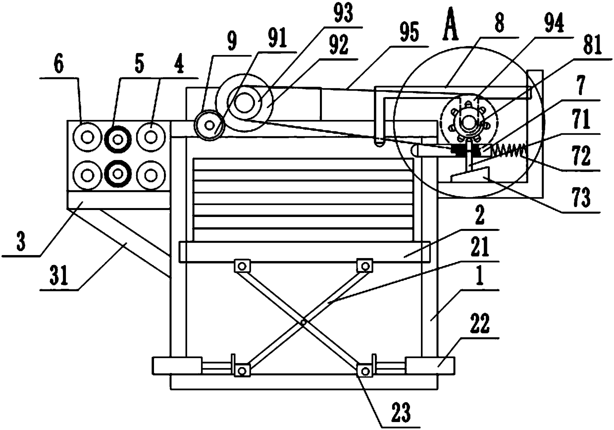
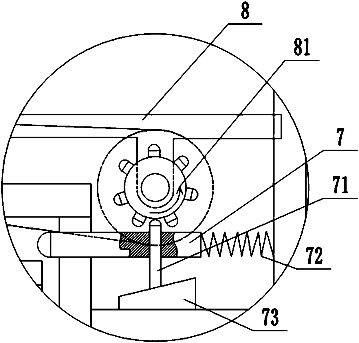
[0018] The reference signs in the drawings of the description include: frame 1, lifting plate 2, connecting rod 21, hydraulic cylinder 22, movable block 23, horizontal plate 3, inclined plate 31, input roller 4, cleaning roller 5, output roller 6, Push rod 7, latch 71, spring 72, wedge block 73, movable frame 8, gear 81, roller 9, driving wheel 91, driven wheel 92, first pulley 93, second pulley 94, belt 95.

[0019] The embodiment is basically as attached figure 1 and figure 2 Shown:

[0020] The automatic sheet material feeding device includes a frame 1, a lifting mechanism and a conveying mechanism. The lifting mechanism is installed in the frame 1, and the conveying mechanism is installed on the upper side of the frame 1. It also includes a pushing mechanism and a reset mechanism installed on the frame 1. mechanism, the push mechanism includes a push rod 7, a latch 71, and a ...


PUM

PropertyMeasurementUnit
angleaaaaaaaaaa

Abstract

The invention relates to the technical field of machining devices of cutting machines, and discloses an automatic plate feeding device. The automatic plate feeding device comprises a machine frame, alifting mechanism and a conveying mechanism; the lifting mechanism is arranged in the machine frame, and the conveying mechanism is arranged on one side of the upper end of the machine frame; the device further comprises a pushing mechanism and a reset mechanism, wherein the pushing mechanism and the reset mechanism are installed on the machine frame; the pushing mechanism comprises a push rod, aplug pin and a spring, the push rod is slidably connected to the machine frame, and one end of the push rod extends into the machine frame; the end, far away from the interior of the machine frame, ofthe push rod is connected to the machine frame through the spring, and the plug pin is connected to the rod surface of the push rod. According to the automatic plate feeding device, through the cooperation of the pushing mechanism and the reset mechanism, the plate layer on the uppermost layer can be pushed out periodically, each plate in the plate layer is separated one by one is guaranteed, conveying is realized, and the problem that plates cannot be fed one by one in the prior art is solved.

Description

technical field [0001] The invention relates to the technical field of cutting machining equipment. Background technique [0002] At present, in the production of laser cutting equipment for processing and preparing parts for metal sheets, due to the lack of professional feeding tools, currently the operator mainly realizes the loading of metal sheets by operating the traditional lifting mechanism and coordinating with the conveying roller table. Although this method can meet the needs of the feeding operation, its work efficiency is low and the labor intensity is relatively large. At the same time, during the transportation and long-term storage of metal plates, on the one hand, a large amount of metal oxide corrosion layer and external dust, oil and other sundries will be formed on the pollutant layer on the surface; Bending radians or even wrinkles, etc., resulting in poor surface quality of metal sheets. When using laser cutting equipment to directly process sheets with...

Claims


Application Information

Patent Timeline
Patent Type & Authority Applications(China)
IPC IPC(8): B23K26/70B23K26/38
CPCB23K26/38B23K26/702
Inventor 李新平
Owner 宁波隆锐机械制造有限公司
Why Eureka
Try Eureka