A design method of four-point support for the bed of a horizontal machining center

A machining center and four-point support technology, used in metal processing equipment, metal processing mechanical parts, manufacturing tools, etc., can solve the problems of difficulty in adjusting the level of the bed and large deformation of the guide rail of the bed, and achieve the purpose of suppressing the deformation of the guide rail and reducing the static pressure. The effect of reduced deformation difference and simple and reliable supporting structure

Inactive Publication Date: 2020-04-07
TIANJIN UNIV
View PDF6 Cites 0 Cited by
  • Summary
  • Abstract
  • Description
  • Claims
  • Application Information

AI Technical Summary

Problems solved by technology

The bed structure obtained by the design method of the present invention not only solves the problem that the bed is difficult to adjust the level, but also solves the problem that the bed guide rail has a large deformation difference under the condition of three-point support

Method used


Image

  • A design method of four-point support for the bed of a horizontal machining center
  • A design method of four-point support for the bed of a horizontal machining center
  • A design method of four-point support for the bed of a horizontal machining center

Examples


Embodiment Construction

[0018] The present invention will be further described below in conjunction with the accompanying drawings.

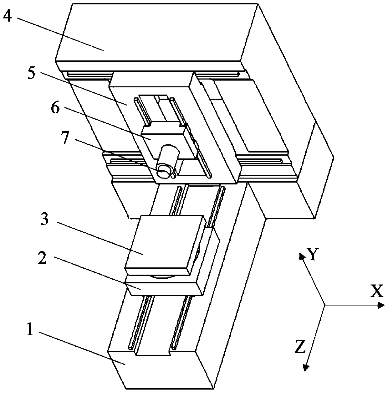
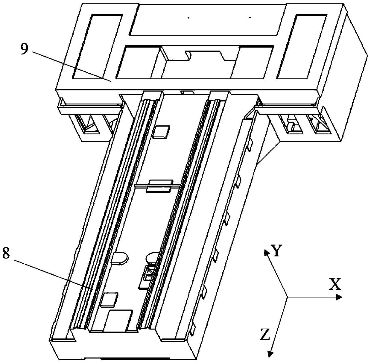
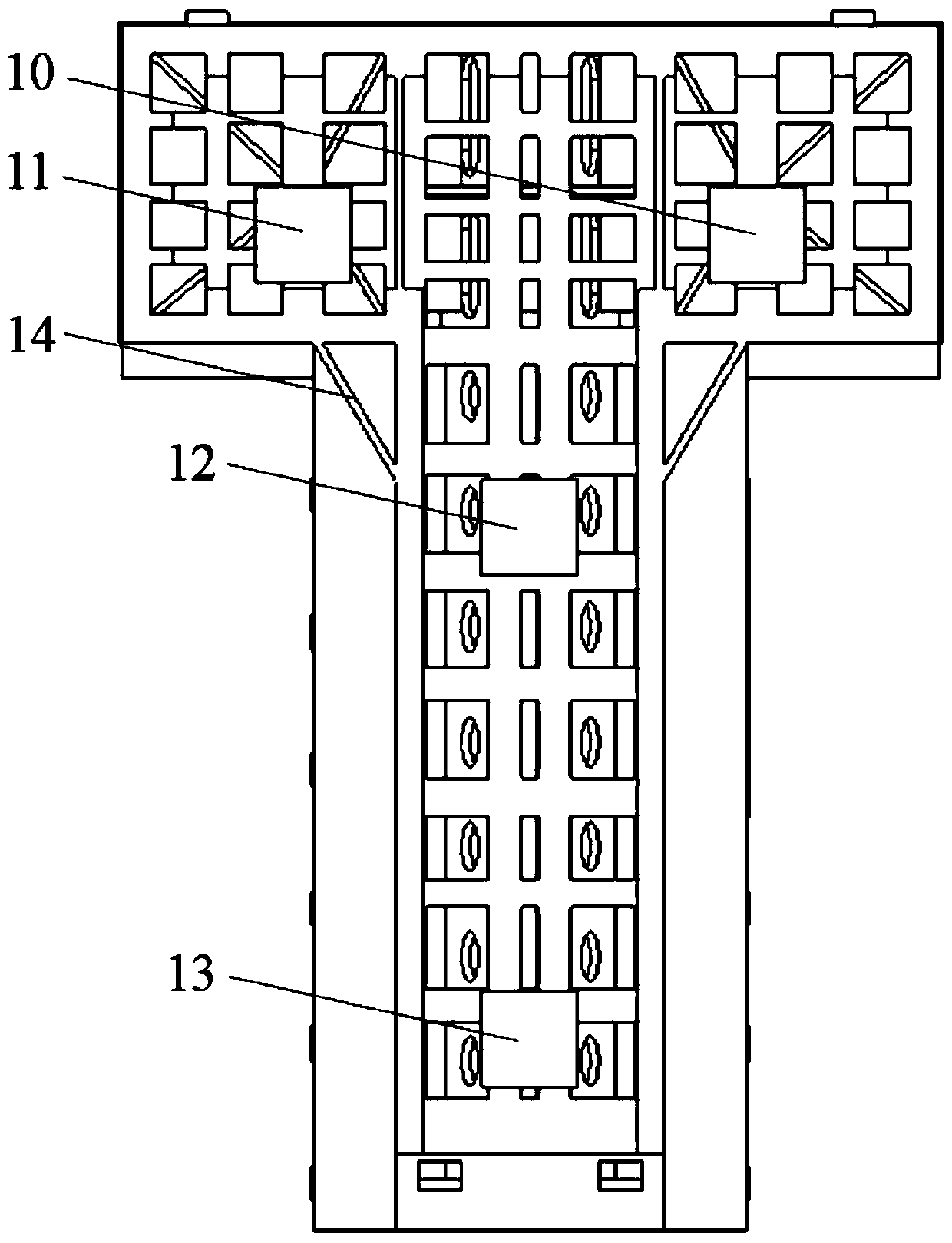
[0019] A bed structure of a horizontal machining center is installed on a machine tool. The machine tool includes a bed 1, a column 4, a sliding plate 5, a spindle box 6, and a workbench 3; the structure of the bed 1 is a T-shaped bed as a whole, and the structure of the bed 1 The bottom has four support structures, the two supports at the rear of the bed 1 are distributed along the X direction, and the two supports at the front of the bed 1 are distributed along the Z direction, which are used to support the bed 1 on the ground foundation; the front end of the upper part of the bed 1 is installed Guide rail, workbench 3 is installed on the guide rail, column 4 is installed at the rear of the bed, slide plate 5 and spindle box 6 are installed on the column 4.

[0020] The support structure at the bottom of the bed structure of the horizontal machining center refers to ...


PUM


Abstract

The invention discloses a horizontal machining center lathe bed four-point supporting design method. According to the horizontal machining center lathe bed four-point supporting design method, firstly, all structural components of a machine tool are subjected to corresponding treatment, and a horizontal machining center whole machine fine-element model is built; secondly, an obtained lathe bed structure simplified model is used for lathe bed structure simulation; then obtained four-point supporting model static deformation data serve as benchmarks, and the Z-direction coordinate of a supporting shim plate serves as a variable to analyze the static deformation condition of a lathe bed guiding rail; and at last, the difference of whole machine terminal deformation and lathe bed guiding railstatic deformation is controlled within a set value to conduct design for target optimization. According to the lathe bed structure obtained through the design method, the problems that a lathe bed can not to be adjusted to be horizontal easily and the deformation difference of the lathe bed is large under the condition of three-point supporting are solved, and a good guiding effect is achieved for the four-point supporting structure design of the machine tool.

Description

technical field [0001] The invention relates to the field of numerical control machine tool design, in particular to a design method for four-point support of a bed of a horizontal machining center. Background technique [0002] The horizontal machining center is a kind of machine tool. Its bed is located at the lower part of the machine tool, and together with the column, slide plate, spindle box, worktable, etc., it forms the entire horizontal machining center, which supports the entire machine tool. However, because the bed of the existing horizontal machining center adopts multi-point support when supporting, too many support points can easily cause excessive positioning of the machine tool during installation and commissioning, making it difficult to adjust the bed level, and resulting in large plastic creep. In the case of three-point support, due to the long Z-direction of the bed of the horizontal machining center, the support at the front end of the bed will be insu...

Claims


Application Information

Patent Timeline
Patent Type & Authority Patents(China)
IPC IPC(8): B23Q1/01
CPCB23Q1/015
Inventor 张士岳张大卫石一光
Owner TIANJIN UNIV
Why Eureka
Try Eureka