
Door casing milling device

A groove milling device and door sleeve technology, applied in the field of door and window processing, can solve the problems of large cutting amount, large load, and easy damage of the milling cutter.

Active Publication Date: 2020-12-15
重庆百昶智能家居有限公司
View PDF13 Cites 0 Cited by
  • Summary
  • Abstract
  • Description
  • Claims
  • Application Information

AI Technical Summary

Problems solved by technology

However, since there is only one milling cutter, the cutting amount of the milling cutter is large and the load is heavy when milling slots, so the milling cutter is easily damaged

Method used


Image

  • Door casing milling device
  • Door casing milling device

Examples


Embodiment Construction

[0019] The present invention will be described in further detail below by means of specific embodiments:

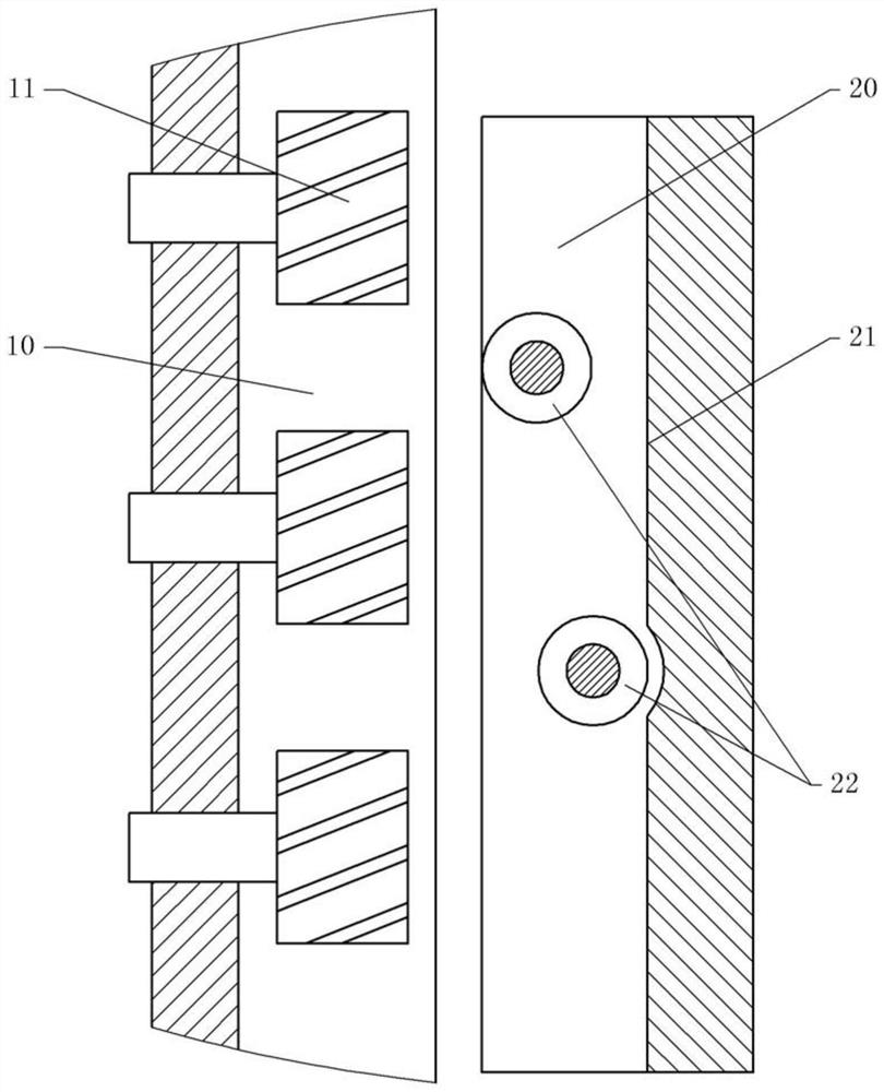
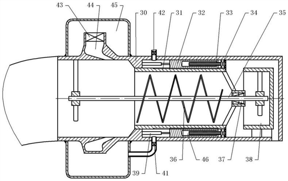
[0020] The reference signs in the accompanying drawings of the description include: bed 10, feed roller 11, tool holder 20, datum surface 21, milling cutter 22, air duct 30, feed pipe 31, piston 32, slide rod 33, press nozzle 34, Rotating shaft 35, spiral guide piece 36, one-way bearing 37, sleeve pipe 38, reciprocating cylinder 39, air outlet check valve 41, intake check valve 42, solenoid valve 43, high-pressure air inlet 44, high-pressure chamber 45, air chamber 46.

[0021] The slot milling device of the door cover in this embodiment includes a bed 10, a feeding mechanism, a slot milling mechanism and a dust removal mechanism. Such as figure 1 As shown, the feeding mechanism includes several feed rollers 11 that are rotatably connected to the bed 10, and the first drive motor that drives the feed rollers 11 to rotate is installed on the bed 10; the plate is placed o...


PUM


Abstract

The invention relates to the technical field of door and window machining and specifically discloses a door pocket groove-milling device which comprises a bed body, a feeding mechanism and a groove-milling machining mechanism, wherein the feeding mechanism and the groove-milling machining mechanism are arranged on the bed body. The feeding mechanism comprises a plurality of feeding rollers rotatably connected with the bed body. The bed body is provided with a first driving mechanism for driving the feeding rollers to rotate. The groove-milling machining mechanism comprises a tool apron fixed on the bed body and a plurality of milling cutters, wherein the milling cutters are arranged in the feeding direction of the feeding mechanism in sequence. The milling cutters are rotatably connected with the tool apron and a datum face used for limiting door plank edges is arranged on the tool apron. In the feeding direction of the feeding mechanism, a vertical distance between a rotating center of the milling cutters and the datum face increases gradually. The vertical distance of a plane passing through a rotating center of two adjacent milling cutters and being parallel to the datum face issmaller than the diameter of the milling cutters. A second driving mechanism used for driving the milling cutters to rotate is arranged on the bed body. The door pocket groove-milling device can reduce cutting quantity and loads of the milling cutters and lower damage probability of the milling cutters when milling a groove.

Description

technical field [0001] The invention relates to the technical field of door and window processing, in particular to a slot milling device for a door cover. Background technique [0002] A wooden door usually consists of a plurality of wooden boards to form a door frame, and then the middle part of the door frame is closed by wooden boards to form a door. When processing the wooden boards that make up the door frame of the wooden door, milling is usually performed on the wooden boards in terms of aesthetics and installation requirements. [0003] Slot milling is performed by a milling cutter, which is the main tool for milling. At present, when milling a wooden board, it is usually performed on a special milling device, which mainly includes a feeding mechanism and a milling mechanism. The feeding mechanism is composed of several feeding rollers, through which the wooden board can be pushed forward; the milling mechanism includes a rotating milling cutter, when the feeding m...

Claims


Application Information

Patent Timeline
Patent Type & Authority Patents(China)
IPC IPC(8): B27F5/12
CPCB27F5/12
Inventor 文泉
Owner 重庆百昶智能家居有限公司
Learn More