
Variable-rigidity rubber suspension with energy recovery function

An energy recovery and rubber technology, applied in electromechanical devices, power devices, jet propulsion devices, etc., can solve the problems of underutilization of vibration energy, inability to provide large dynamic stiffness and damping loss angle, etc., and achieve automatic stiffness adaptation. , the effect of damping vibration and improving utilization

Active Publication Date: 2018-09-04
HEFEI UNIV OF TECH
View PDF8 Cites 1 Cited by
  • Summary
  • Abstract
  • Description
  • Claims
  • Application Information

AI Technical Summary

Problems solved by technology

[0005] Aiming at the deficiencies of the prior art, the present invention provides a rubber mount with energy recovery function and variable stiffness, which has the advantages of energy saving, low cost, simple structure and large output power, etc. When vibrating, it cannot provide a large dynamic stiffness and damping loss angle, and the vibration energy is not fully utilized.

Method used


Image

  • Variable-rigidity rubber suspension with energy recovery function
  • Variable-rigidity rubber suspension with energy recovery function
  • Variable-rigidity rubber suspension with energy recovery function

Examples


Embodiment 1

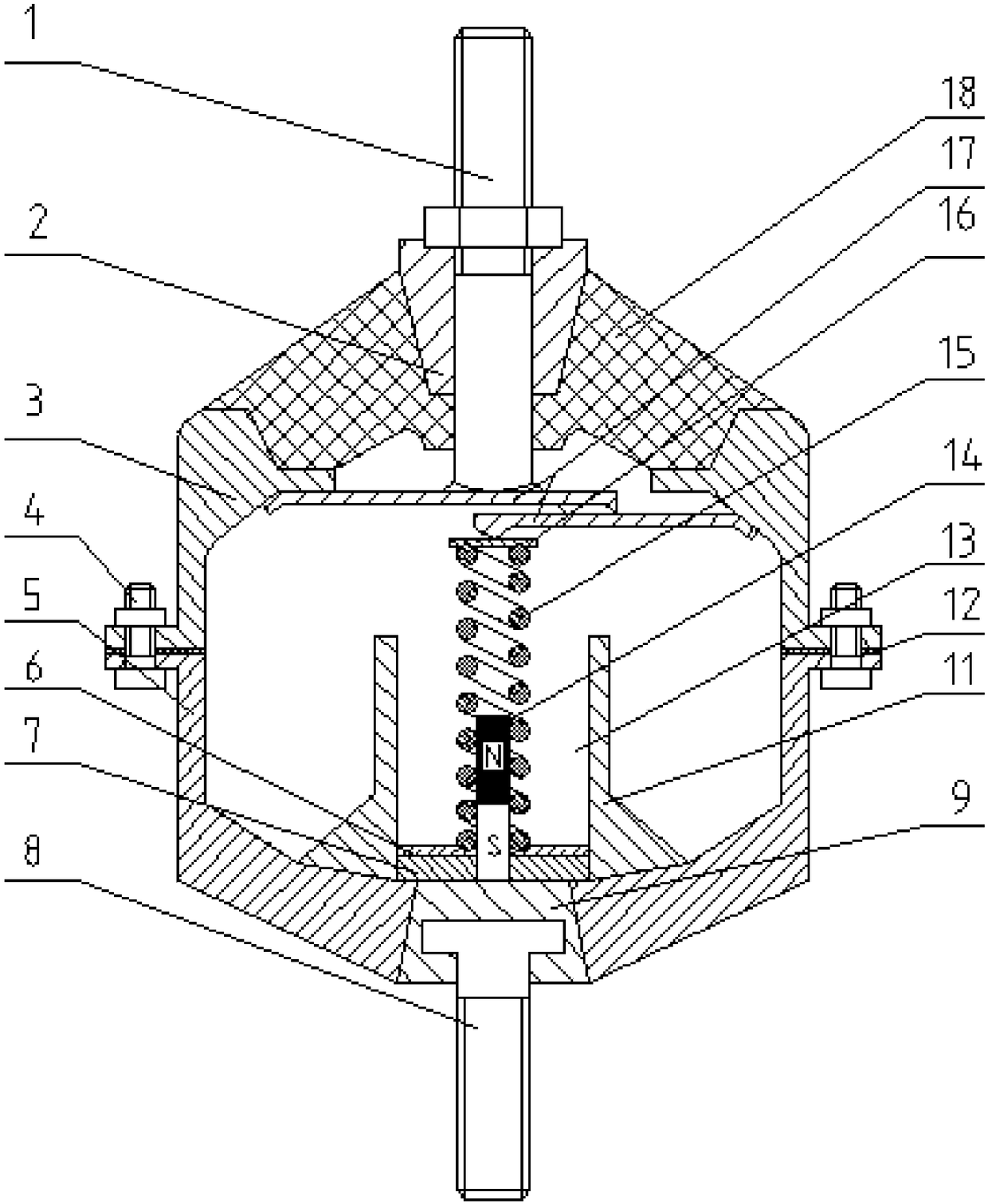
[0043] see figure 1 , the rubber mount with energy recovery function and variable stiffness in this embodiment includes an upper bolt 1, an upper core 2, an upper frame 3, a rubber main spring 18, a lower bolt 8, a lower core 9, a lower frame 5, a fixed Bolt 4, displacement amplification mechanism 17, power generation mechanism, step-up rectification circuit, rubber fixing piece 11.

[0044] The upper bolt 1 is fixed on the engine, the upper core 2 wraps the side of the upper bolt 1 , the rubber main spring 18 wraps the upper core 2 , and the upper frame 3 is installed on the bottom of the rubber main spring 18 . The lower frame 5 is fixed on the upper frame 3 by the fixing effect of the fixing bolt 4, the lower core body 9 is installed on the gap at the bottom of the lower frame 5 and seals the gap, the top of the lower bolt 8 is inserted into the lower core body 9, and the bottom of the lower bolt 8 The bottom end is mounted on the frame. Wherein, the upper skeleton 3 and ...

Embodiment 2

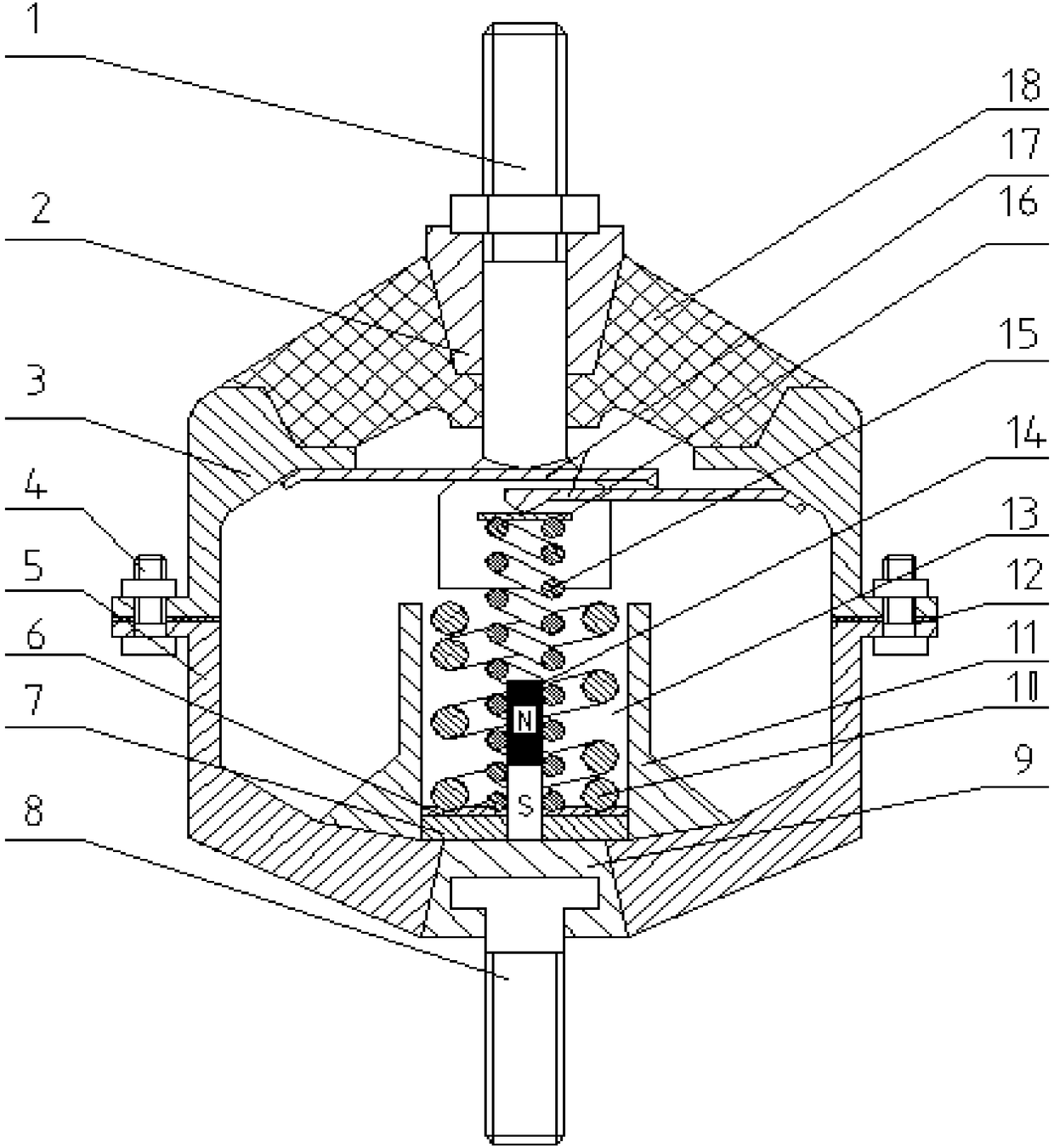
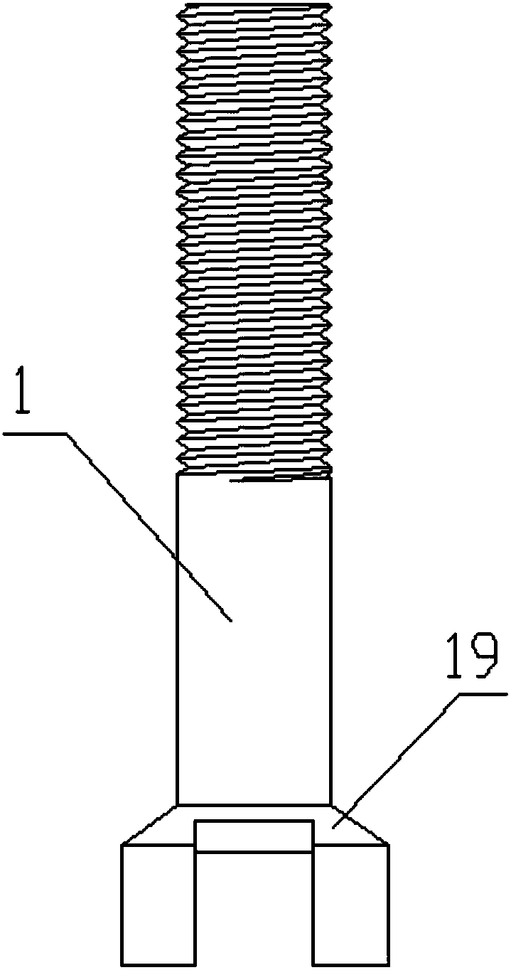
[0051] see figure 2 The rubber suspension with energy recovery function and variable stiffness of this embodiment is similar to the rubber suspension of Embodiment 1, and the only difference is that the power generating mechanism of this embodiment also includes a spring 2 10, and the upper bolt 1 extends on There are two stoppers 19 oppositely arranged on the end face of one end in the cavity, and the overlap between the upper pressing piece and the lower pressing piece is located between the two stoppers 19 (please combine image 3 , Figure 4 and Figure 5 ). Spring two 10 is sleeved outside spring one 15, and rigidity is stronger than the rigidity of spring one 15, and the height of spring two 10 under natural state is less than the height of spring one 15 under natural state. The spring one 15 overlaps on one end of the lower pressing piece and is located between the two stoppers 19, the two stoppers 19 are located above the spring two 10, and are pressed down by the ...

Embodiment 3

[0056] see Figure 6 , the rubber mount with energy recovery function and variable stiffness in this embodiment is similar to the rubber mount in Embodiment 2, and the only difference is that the spring 10 in this embodiment does not use an external power supply, and the rubber mount 11 The inner wall of the inner wall is provided with a magnetic sheet 20 surrounding the spring two 10, and the magnetic field generated by the magnetic sheet 20 is in the same direction as the magnetic field produced by the magnet 14, thereby enhancing the strength of the magnetic field where the spring one 15 is located, improving the power generation efficiency, and thereby enhancing the energy conversion efficiency.


PUM


Abstract

The invention discloses a variable-rigidity rubber suspension with an energy recovery function. The variable-rigidity rubber suspension comprises a shell, an upper bolt, a displacement amplifying mechanism and a power generating mechanism. One end of the upper bolt is inserted into the shell to extend into a cavity of the shell, and the displacement amplifying mechanism and the power generating mechanism are mounted in the cavity. The displacement amplifying mechanism comprises an upper pressure plate and a lower pressure plate, one end of the upper pressure plate and one end of the lower pressure plate are fixed to two opposite sides of the inner wall of the cavity respectively, the other end of the upper pressure plate and the other end of the lower pressure plate are both free ends andin lap joint vertically, and one end, extending into the cavity, of the upper bolt is mounted on the upper pressure plate. A first spring provides low rigidity in high-frequency small-amplitude vibration of the suspension, a second spring provides high rigidity in low-frequency large-amplitude vibration of the suspension, and accordingly rigidity auto-adaption of the suspension is realized, effectiveness in attenuation of vibration of a power assembly is achieved, suspension vibration energy recovery is realized, and the energy utilization rate is increased.

Description

technical field [0001] The invention relates to a rubber mount in the technical field of mounts, in particular to a rubber mount with energy recovery function and variable rigidity. Background technique [0002] The dynamic stiffness characteristic of the metal spring increases zigzagging with the increase of the vibration frequency. In the first-order resonance region, the dynamic stiffness of the spring is much smaller than the static stiffness. In the first-order anti-resonance region, the spring can produce a large nonlinear dynamic stiffness, and near the first-order anti-resonance frequency, the value of the dynamic stiffness increases first and then decreases. Metal springs have a better shock absorption effect at low frequencies, so they are generally used for suspensions. [0003] As the damping element of the automobile powertrain, the mount is required to bear the mass of the entire powertrain, and it is also required to have large stiffness and large damping ch...

Claims


Application Information

Patent Timeline
Patent Type & Authority Applications(China)
IPC IPC(8): B60K5/12H02K35/02F03G7/08
CPCB60K5/1208F03G7/08H02K35/02
Inventor 胡金芳高东阳朱冬东
Owner HEFEI UNIV OF TECH
Learn More