A rubber mount with energy recovery and variable stiffness
A technology of energy recovery and rubber, which is applied in the direction of power devices, electromechanical devices, jet propulsion devices, etc., can solve the problems of not being able to provide large dynamic stiffness and damping loss angle, and vibration energy not being fully utilized, so as to achieve automatic stiffness adaptation , Attenuate vibration and improve utilization
- Summary
- Abstract
- Description
- Claims
- Application Information
AI Technical Summary
Problems solved by technology
Method used
Image
Examples
Embodiment 1
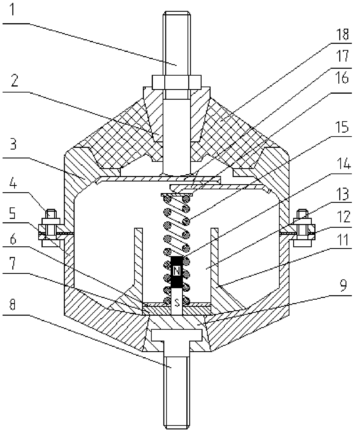
[0043] see figure 1 , the rubber mount with energy recovery function and variable stiffness in this embodiment includes an upper bolt 1, an upper core 2, an upper frame 3, a rubber main spring 18, a lower bolt 8, a lower core 9, a lower frame 5, a fixed Bolt 4, displacement amplification mechanism 17, power generation mechanism, step-up rectification circuit, rubber fixing piece 11.
[0044] The upper bolt 1 is fixed on the engine, the upper core 2 wraps the side of the upper bolt 1 , the rubber main spring 18 wraps the upper core 2 , and the upper frame 3 is installed on the bottom of the rubber main spring 18 . The lower frame 5 is fixed on the upper frame 3 by the fixing effect of the fixing bolt 4, the lower core body 9 is installed on the gap at the bottom of the lower frame 5 and seals the gap, the top of the lower bolt 8 is inserted into the lower core body 9, and the bottom of the lower bolt 8 The bottom end is mounted on the frame. Wherein, the upper skeleton 3 and ...
Embodiment 2
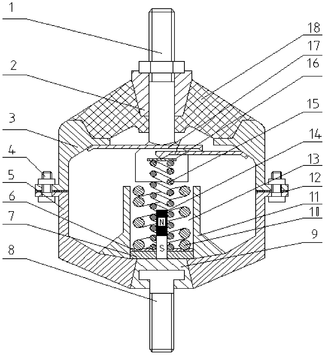
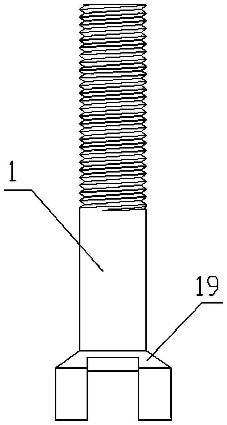
[0051] see figure 2 The rubber suspension with energy recovery function and variable stiffness of this embodiment is similar to the rubber suspension of Embodiment 1, and the only difference is that the power generating mechanism of this embodiment also includes a spring 2 10, and the upper bolt 1 extends on There are two stoppers 19 oppositely arranged on the end face of one end in the cavity, and the overlap between the upper pressing piece and the lower pressing piece is located between the two stoppers 19 (please combine image 3 , Figure 4 and Figure 5 ). Spring two 10 is sleeved outside spring one 15, and rigidity is stronger than the rigidity of spring one 15, and the height of spring two 10 under natural state is less than the height of spring one 15 under natural state. The spring one 15 overlaps on one end of the lower pressing piece and is located between the two stoppers 19, the two stoppers 19 are located above the spring two 10, and are pressed down by the ...
Embodiment 3
[0056] see Image 6 , the rubber mount with energy recovery function and variable stiffness in this embodiment is similar to the rubber mount in Embodiment 2, and the only difference is that the spring 10 in this embodiment does not use an external power supply, and the rubber mount 11 The inner wall of the inner wall is provided with a magnetic sheet 20 surrounding the spring two 10, and the magnetic field generated by the magnetic sheet 20 is in the same direction as the magnetic field produced by the magnet 14, thereby enhancing the strength of the magnetic field where the spring one 15 is located, improving the power generation efficiency, and thereby enhancing the energy conversion efficiency.
PUM
 Abstract
Description
Claims
Application Information
 - R&D
- Intellectual Property
- Life Sciences
- Materials
- Tech Scout
- Unparalleled Data Quality
- Higher Quality Content
- 60% Fewer Hallucinations
Browse by: Latest US Patents, China's latest patents, Technical Efficacy Thesaurus, Application Domain, Technology Topic, Popular Technical Reports.
© 2025 PatSnap. All rights reserved.Legal|Privacy policy|Modern Slavery Act Transparency Statement|Sitemap|About US| Contact US: help@patsnap.com


