
Chip programming device

A burner and chip technology, which is applied in the direction of conveyor objects, transportation and packaging, packaging, etc., can solve the problems of poor versatility and high equipment cost, achieve the effects of small occupancy rate, reduce equipment cost, and improve versatility

Active Publication Date: 2018-09-04
SUZHOU XINHUARUI ELECTRONICS
View PDF10 Cites 5 Cited by
  • Summary
  • Abstract
  • Description
  • Claims
  • Application Information

AI Technical Summary

Problems solved by technology

[0003] In view of the above problems, the present invention provides a chip burner, which can solve the problems of poor versatility and high equipment cost caused by the existing chip burner because it can only be applied to a single chip feeding mode

Method used


Image

  • Chip programming device
  • Chip programming device
  • Chip programming device

Examples


Embodiment Construction

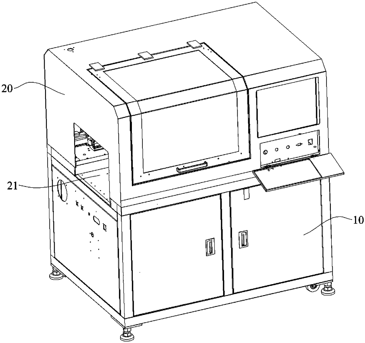
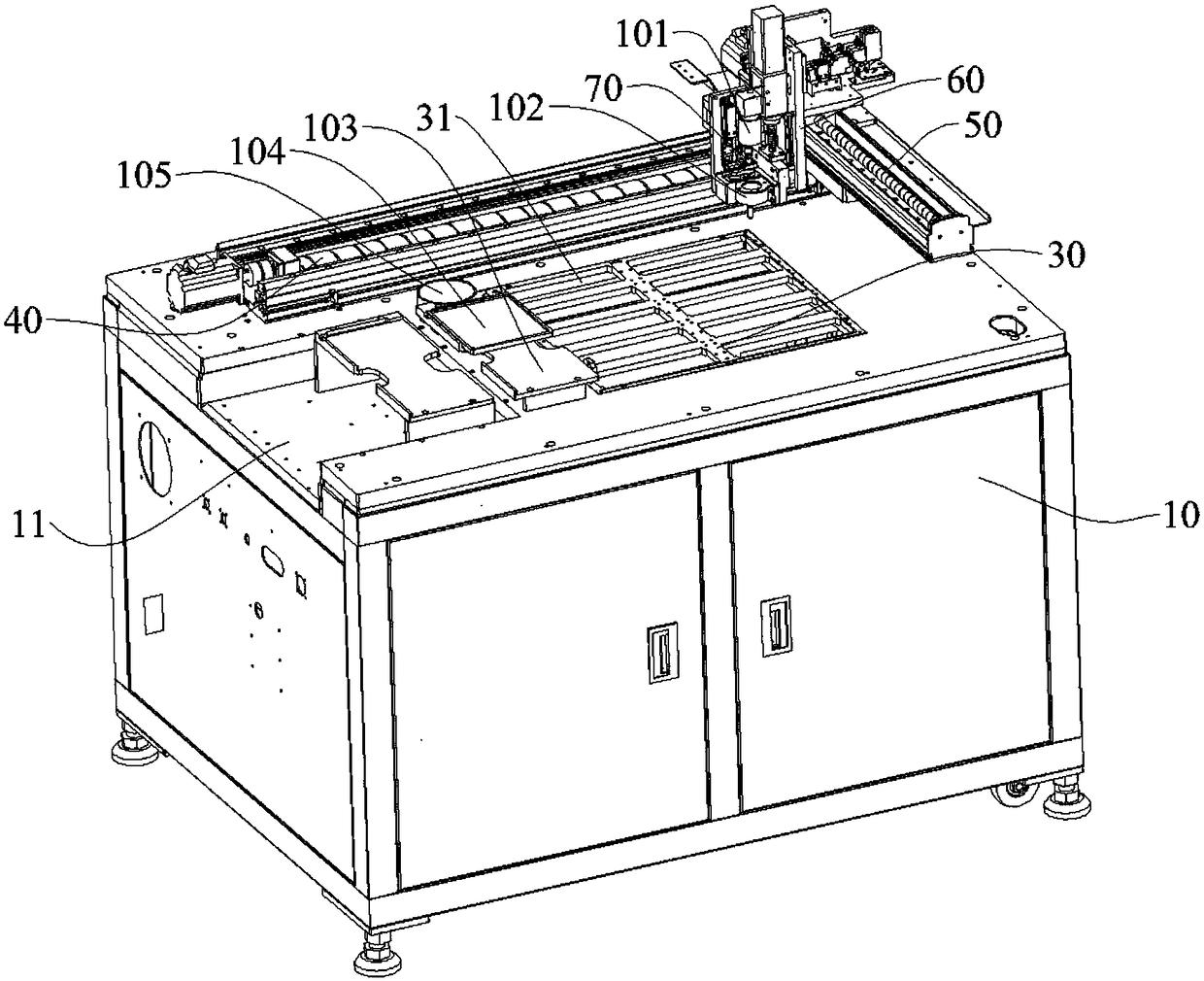
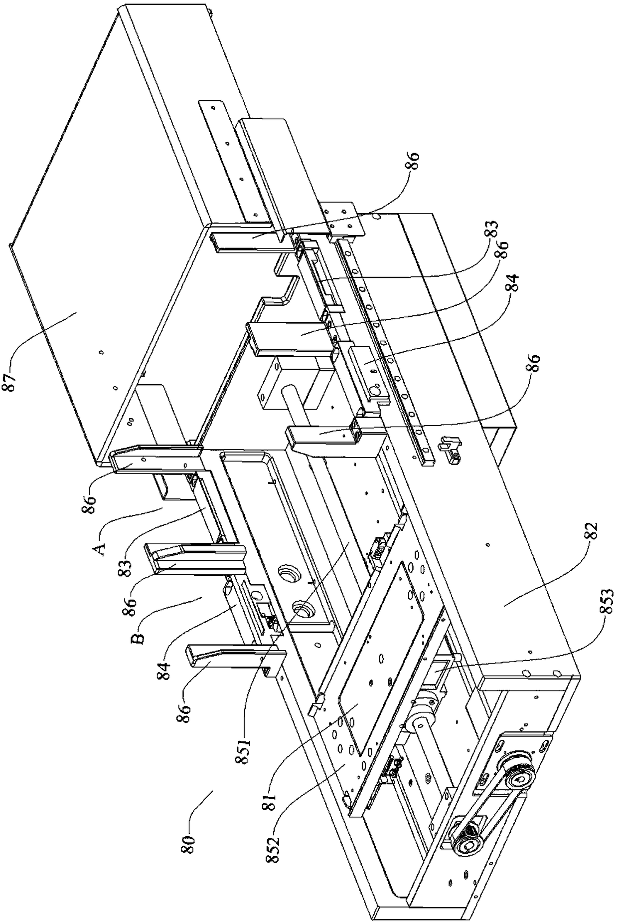
[0029] See figure 1 and figure 2 , the chip burning machine of the present invention, it comprises machine platform 10 and chip absorbing device 70, and machine platform 10 is provided with chip burning area, and on the chip burning area, burner is installed by burner holder 30, and chip burning The longitudinal rear side of the recording area is provided with a horizontal linear module 40, the chip suction device 70 is installed on the vertical lifting mechanism 60, the vertical lifting mechanism 60 is connected to the vertical linear module 50, and the vertical linear module 50 is connected to the horizontal linear module 40; it also includes a tray-mounted chip feeder 80 and / or a tape chip feeder 90, a box-shaped cover 20 is provided on the machine table 10, and a feed inlet is provided at the bottom of the left side wall of the box-shaped cover 20 21. A sunken platform 11 is provided at the position where the machine 10 is facing the feed port 21, and the discharge end o...


PUM


Abstract

The invention provides a chip programming device. The chip programming device can solve the problems that the universality is poor, and the equipment cost is high due to the fact that an existing chiprecorder can only be suitable for a single chip feeding mode. The chip programming device comprises a machine table and a chip sucking device, and further comprises a disc-mounted chip feeding deviceand / or a braided chip feeding device; a chip programming area is arranged on the machine table; programmers are arranged on the chip programming area through a programmer fixing base; a box-shaped cover cap is arranged on the machine table; a feed port is formed in the bottom of the left side wall of the box-shaped cover cap; a sunken platform is arranged at the position, right opposite to the feed port, of the machine table; the discharging end of the disc-mounted chip feeding device and / or the braided chip feeding device extends into the box-shaped cover cap through the feed port and is detachably arranged on the sunken platform; and ten programmer mounting ports are formed in the programmer fixing base.

Description

technical field [0001] The invention relates to the technical field of chip programming, in particular to a chip programming machine. Background technique [0002] Usually, the package of the chip adopts a tape package or a tray package. Due to the difference between the two chip packages, the loading and unloading forms of the chip programming machine are completely different, which makes the programming of chips with different packages must be To configure chip programming machines with different loading and unloading forms, the two loading and unloading forms of the programming machines cannot be used in common, which leads to the problem of high equipment cost. Contents of the invention [0003] In view of the above problems, the present invention provides a chip programming machine, which can solve the problems of poor versatility and high equipment cost of the existing chip programming machine because it can only be applied to a single chip feeding mode. [0004] Th...

Claims


Application Information

Patent Timeline
Patent Type & Authority Applications(China)
IPC IPC(8): B65G47/91B65B15/04
CPCB65B15/04B65G47/912
Inventor 陈冬兵
Owner SUZHOU XINHUARUI ELECTRONICS
Learn More