
Construction process for manhole cover device on road

A construction technology and well inspection technology, which is applied in the municipal field, can solve problems such as the easy aging of neoprene rubber pads, the increase in the height difference between the well frame and the well cover, and disturbance, and achieve fast construction, increased anti-fall function, and small construction surface Effect

Active Publication Date: 2018-09-04
TIANJIN JUSHI TECH DEV
View PDF6 Cites 9 Cited by
  • Summary
  • Abstract
  • Description
  • Claims
  • Application Information

AI Technical Summary

Problems solved by technology

[0005] 2. The construction quality problem of subsidence of the road inspection well cover is difficult to solve. The main reason is that the well frame is not firmly embedded in the ordinary C30 concrete. There are two main reasons for this problem. (1) The next step of construction disturbs the ordinary C30 concrete. For example, when the surface layer is rolled, the vibratory roller rolls the manhole cover; (2) the disturbance of ordinary C30 concrete by traffic vehicles; currently, these two disturbances of ordinary C30 concrete are almost impossible to solve
[0006] 3. The problem of manhole covers. At present, most of the wells use ductile iron manhole covers. Manhole cover manufacturers add neoprene rubber pads to prevent the manhole covers from jumping. Neoprene rubber pads are easy to age and need to be replaced regularly. If it is not timely, there will be bouncing sound. After a long time, the height difference between the well frame and the well cover will increase, and the bouncing sound will become more serious.

Method used


Image

  • Construction process for manhole cover device on road
  • Construction process for manhole cover device on road
  • Construction process for manhole cover device on road

Examples


Embodiment Construction

[0046] The following will clearly and completely describe the technical solutions in the embodiments of the present invention with reference to the accompanying drawings in the embodiments of the present invention. Obviously, the described embodiments are only some, not all, embodiments of the present invention. Based on the embodiments of the present invention, all other embodiments obtained by persons of ordinary skill in the art without making creative efforts belong to the protection scope of the present invention.

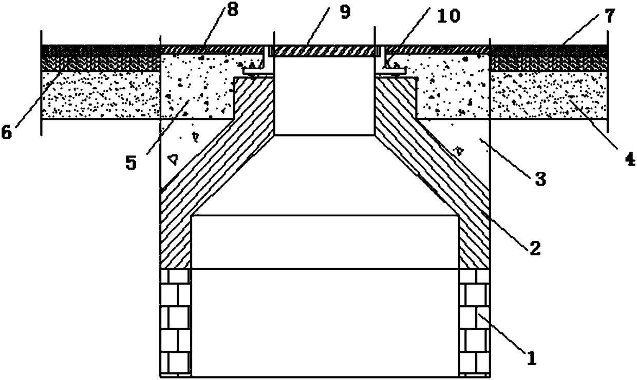
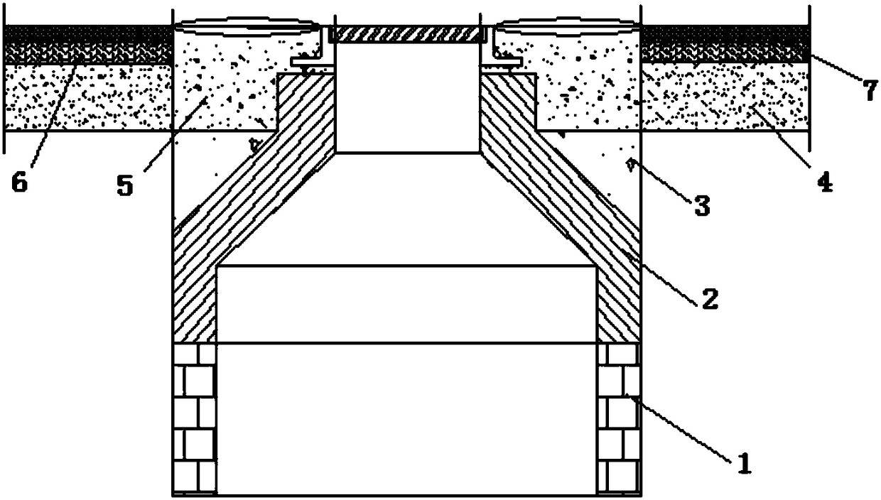
[0047] see Figure 1-3 , 1. After the construction of the well body 1 is completed, the wellhead is closed with a steel plate, and the road is applied on it.

[0048] Subgrade 4 and surface structure;

[0049] 2. The well neck 2 is installed by reverse slotting, the outer wall of the well neck 2 is manually rubbed, and the gap is backfilled with C10 concrete, and it is compacted by vibration;

[0050] 3. The well circle 10 is leveled with wedge-shaped C30 co...


PUM


Abstract

The invention discloses a construction process for a manhole cover device on a road. The construction process for the manhole cover device on the road comprises the steps of breaking an asphalt concrete and a part of base layer, blowing off scums on the periphery through high pressure air, spraying water for wetting, leveling for stabilizing a well curb, erecting a form on the inner side of the well curb, mixing a super-early strength black C30 concrete, and pouring the concrete. According to a process technology for solving the problems of sinking and instability of a manhole cover, the sinking problem of the manhole cover is solved by using a technological achievement of rising a manhole through the super-early strength black concrete, a manhole cover installing or a sunken manhole covermaintaining process, and a combined application technology of the technological achievement of rising the manhole through the super-early strength black concrete and a novel composite manhole cover;a back circle problem of the 'technological achievement of rising the manhole through the super-early strength black concrete' is solved; the instability problem of the manhole cover is solved; an anti-falling problem is further solved according to the needs; and through the two process technologies, the aims of small construction surface, timeliness and quickness can be achieved.

Description

technical field [0001] The present invention (invention) belongs to the field of municipal technology, and relates to an installation (method) of inspection well covers on roads. The technology is applied to the installation and construction of inspection well covers on newly built or repaired roads. Background technique [0002] With the increase in the share of family cars in our country, people have also paid great attention to urban road facilities, which immediately highlighted the common problems of urban road facilities. Among them, the subsidence of the manhole cover and the sound of the manhole cover on the road are the most discussed issues. It has not been fully resolved for many years. This problem not only increases the difficulty, workload and maintenance cost of road maintenance, but also is a source of safety risk that causes traffic accidents. At present, most urban roads in my country use lime-stabilized soil, lime-fly ash stabilized soil, lime-fly ash-sta...

Claims


Application Information

Patent Timeline
Patent Type & Authority Applications(China)
IPC IPC(8): E02D29/14
CPCE02D29/14
Inventor 田志刚
Owner TIANJIN JUSHI TECH DEV
Learn More