
End reinforcing type steel-concrete composite pipe

A combination pipe and reinforced technology, applied in the direction of structural elements, building components, building insulation materials, etc., can solve the problems of slow construction progress, poor corrosion resistance, poor fire performance, etc., to improve construction progress, reduce weight, improve The effect of anti-alteration properties

Inactive Publication Date: 2018-09-04
HENAN LYUJIAN BUILDING TECH CO LTD
View PDF0 Cites 0 Cited by
  • Summary
  • Abstract
  • Description
  • Claims
  • Application Information

AI Technical Summary

Problems solved by technology

[0003] The components of the existing prefabricated buildings have the following technical problems: 1. Poor fire protection performance; 2. Poor corrosion resistance 3. Complex procedures during on-site construction and slow construction progress; 4. High cost

Method used


Image

  • End reinforcing type steel-concrete composite pipe
  • End reinforcing type steel-concrete composite pipe
  • End reinforcing type steel-concrete composite pipe

Examples


Embodiment 1

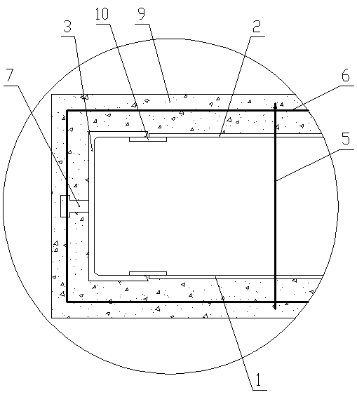
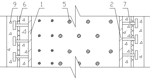
[0023] Embodiment one: if Figure 1-Figure 4 As shown, the end-reinforced steel-concrete composite pipe of the present invention includes an inner steel plate 1 and an outer steel plate 2 arranged vertically and parallel to each other, between the left edge of the inner steel plate 1 and the left edge of the outer steel plate 2 A left reinforced steel 3 is provided, and a right reinforced steel 4 is arranged between the right edge of the inner steel plate 1 and the right edge of the outer steel plate 2, and the horizontal sections of the left reinforced steel 3 and the right reinforced steel 4 are in the shape of “[”, The left reinforced section steel 3 and the right reinforced section steel 4 are left and right symmetrical and the openings are oppositely arranged. The inner steel plate 1, the outer steel plate 2, the left reinforced section steel 3 and the right reinforced section steel 4 are enclosed to form a vertically transparent rectangular cylindrical structure. The inne...

Embodiment 2

[0032] Embodiment 2: as Figure 5 As shown, the difference between this embodiment and the first embodiment is that the rectangular cylindrical structure enclosed by the inner steel plate 1, the outer steel plate 2, the left reinforcing steel 3 and the right reinforcing steel 4 is formed by bending and welding a profiled steel plate. The cross section of the profiled steel plate is in the shape of a triangle, a trapezoid, an arc, a wavy line or a broken line.

Embodiment 3

[0033] Embodiment 3: The difference between this embodiment and Embodiment 1 is that the left reinforced section steel 3 and the right reinforced section steel 4 are both made into a "mouth" or "I" shape in horizontal cross section.


PUM


Abstract

An end reinforcing type steel-concrete composite pipe comprises an up-down through rectangular cylindrical structure which is defined by inner side steel plates, outer side steel plates, left reinforcing profile steel and right reinforcing profile steel. A plurality of tie bars are arranged between the inner side steel plates and the outer side steel plates, the inner ends and the outer ends of the tie bars extend out of the inner side steel plates and the outer side steel plates towards the two sides correspondingly, a steel bar skeleton with the cross section being of a rectangular structureis arranged on the periphery of the outer portion of the rectangular cylindrical structure, gaps are formed between the steel bar skeleton and the rectangular cylindrical structure, concrete is poured on the periphery of the outer portion of the rectangular cylindrical structure, and thus the steel bar skeleton is coagulated. According to the end reinforcing type steel-concrete composite pipe, the construction efficiency is improved, the ductility and compressive strength of the concrete are greatly improved, the plasticity and toughness performance of a whole steel-concrete composite shear wall structure is greatly improved, the anti-deformation ability and compressive strength of a shear wall are greatly improved, and the fireproof and anticorrosion problems are also solved effectively.

Description

technical field [0001] The invention belongs to the technical field of structural engineering, and in particular relates to an end-reinforced steel-concrete composite pipe. Background technique [0002] The components of the prefabricated building can be industrialized in the factory. The components are equivalent to standard products, and they can be installed directly on site. field, has its incomparable superiority; components are produced standardizedly in the factory, the quality is more guaranteed than on-site production, and can be effectively controlled. The high-standard mechanization of components reduces the number of on-site personnel. Both labor cost and safety production are helpful. [0003] The components of existing prefabricated buildings have the following technical problems: 1. Poor fire protection performance; 2. Poor corrosion resistance; 3. Complicated procedures during on-site construction and slow construction progress; 4. High cost. Contents of t...

Claims


Application Information

Patent Timeline
IPC IPC(8): E04C3/00E04B2/56E04B1/94E04B1/64
CPCE04B1/642E04B1/943E04B2/562E04C3/00
Inventor 何博奥杨梦遥何慧贤师国良
Owner HENAN LYUJIAN BUILDING TECH CO LTD
Learn More