Oil and gas separation device for automobile refrigeration system

A refrigeration system and separation device technology, applied in the direction of refrigerators, refrigeration components, refrigeration and liquefaction, etc., can solve the problems of not achieving oil separation efficiency, not achieving separation well, increasing flow rate, etc.

Active Publication Date: 2020-05-22
安徽航嘉汽车零部件制造有限公司
View PDF5 Cites 1 Cited by
  • Summary
  • Abstract
  • Description
  • Claims
  • Application Information

AI Technical Summary

Problems solved by technology

However, after the gas mixed with lubricating oil in the intake pipe blows to the windshield and the flow rate loss occurs, because the diameter of the lower end of the tapered sleeve is larger than the upper end, the linear velocity of the lower end is greater than that of the upper end. When flowing down the sleeve, the flow rate of the lubricating oil increasing, and from the top of the sleeve downwards, the space where the gas is located gradually decreases, and the flow rate of the gas increases again, because the oil-gas separator that uses inertial force changes the flow direction of the mixed oil and gas and reduces the flow rate to achieve the gaseous state. Refrigerant and lubricating oil are separated under the action of different gravity, but this device will increase the flow rate, so the separation cannot be achieved well
And the gas enters the air outlet pipe from the bottom of the sleeve, and the air flow directly blows to the floating plate to generate pressure on the floating plate, so it is inevitable that the gas will mix with the lubricating oil again at the floating plate, and the efficient oil separation cannot be achieved efficiency

Method used


Image

  • Oil and gas separation device for automobile refrigeration system
  • Oil and gas separation device for automobile refrigeration system
  • Oil and gas separation device for automobile refrigeration system

Examples


Embodiment Construction

[0022] The following is a further detailed description through specific implementations:

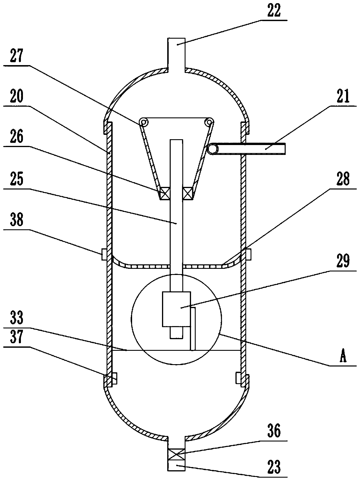
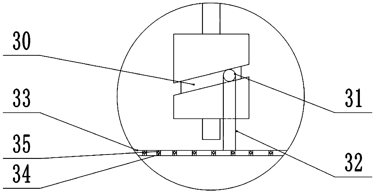
[0023] The reference signs in the drawings of the specification include: housing 20, intake pipe 21, outlet pipe 22, oil return pipe 23, shaft 25, bearing 26, sleeve 27, filter plate 28, cylindrical cam 29, curved groove 30, The sliding block 31, the pin shaft 32, the floating plate 33, the through hole 34, the oil inlet check valve 35, the oil outlet check valve 36, the liquid level gauge 37, the positioning plate 38, and the silencing layer 39.

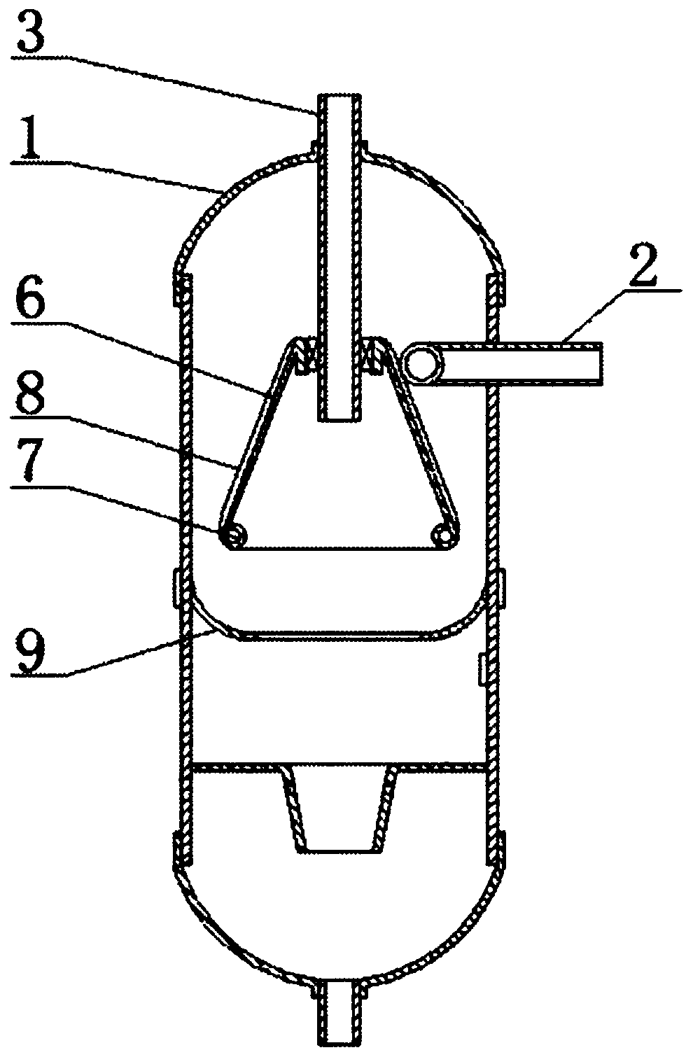
[0024] Such as figure 2 As shown, the oil and gas separation device of the automobile refrigeration system includes an air inlet pipe 21, an air outlet pipe 22, an oil return pipe 23, and a cylindrical shell 20. The outer wall of the cylindrical shell 20 is provided with a circle of positioning plates 38, and the air outlet pipe 22 is arranged in At the center of the top of the housing 20, the air inlet pipe 21 is provided on the side wall of the ...


PUM


Abstract

The invention belongs to the field of refrigeration equipment, in particular to an oil-gas separation device for an automobile refrigeration system. The oil-gas separation device comprises a gas inletpipe, a gas outlet pipe, an oil return pipe and a cylindrical shell, wherein the gas outlet pipe is arranged on the top of the shell; the gas inlet pipe is arranged on an upper side wall of the shell; the oil return pipe is arranged at the bottom of the shell; a shaft rod is arranged under the gas outlet pipe; the upper part of the shaft rod is connected with an inverted-cone shaped sleeve through a bearing; an outer wall of the sleeve is configured as a spiral slideway; the direction of a gas outlet of the gas inlet pipe is tangential to the outer wall of the sleeve; an inner wall of the shell is rotatably connected with an arc filtering plate of which a bottom peripheral part is bent upwards; the shaft rod is fixed to a filter plate and penetrates through the center of the filter plate;the lower part of the shaft rod is provided with a cylindrical cam; the cylindrical cam comprises a curved groove, a sliding block and a pin shaft; the sliding block is connected with the pin shaft and can be slid along the curved groove; the pin shaft is connected with a floating plate which is arranged on the inner wall of the shell in a sliding manner; and a plurality of through holes are formed in the floating plate. According to the oil-gas separation device for the automobile refrigeration system disclosed by the invention, high-efficient separation on oil and gas can be realized.

Description

Technical field [0001] The invention belongs to the field of refrigeration equipment, and specifically discloses an oil and gas separation device of an automobile refrigeration system. Background technique [0002] The oil-air separator has the ability to separate oil from the refrigerant gas mixture, thereby promoting the effective operation of the automobile refrigeration and air-conditioning system and saving energy. The separated oil enters the lubrication system of the compressor through the pipeline to ensure the normal temperature operation of the compressor. Due to the fast intake airflow speed, if the oil cannot be separated from the mixed gas efficiently, the oil will enter the refrigeration system along with the refrigerant gas and affect the refrigeration effect. [0003] Commonly used oil and gas separators have three forms of separation using inertial force, centrifugal force and filtration. The oil separator using inertial force changes the flow direction of the re...

Claims


Application Information

Patent Timeline
Patent Type & Authority Patents(China)
IPC IPC(8): F25B43/02
CPCF25B43/02
Inventor 罗勇
Owner 安徽航嘉汽车零部件制造有限公司
Why Eureka
Try Eureka