Water cooling turbine shell and casting technology thereof

A turbine shell and water-cooling technology, applied in manufacturing tools, casting equipment, molds, etc., can solve the problems of reducing the production cost of castings, low yield of the water-cooled turbine shell process, and high process yield, so as to reduce production costs and solve the The effect of low process yield and lower casting cost

Inactive Publication Date: 2018-09-07
康诺精工有限公司
View PDF0 Cites 3 Cited by
  • Summary
  • Abstract
  • Description
  • Claims
  • Application Information

AI Technical Summary

Problems solved by technology

[0004] The technical problem to be solved by the present invention is to provide a water-cooled turbine casing and its casting process in view of the above deficiencies, which can solve the problem of low yield in the water-cooled turbine casing process, effectively reduce casting costs; As a result, there is no casting defect in the casting; the heavy feeding riser can be omitted, the process yield is high, and the production cost of this type of casting is effectively reduced

Method used


Image

  • Water cooling turbine shell and casting technology thereof
  • Water cooling turbine shell and casting technology thereof
  • Water cooling turbine shell and casting technology thereof

Examples


Embodiment 1

[0027] Embodiment 1 Water-cooled turbine housing

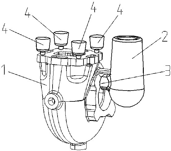
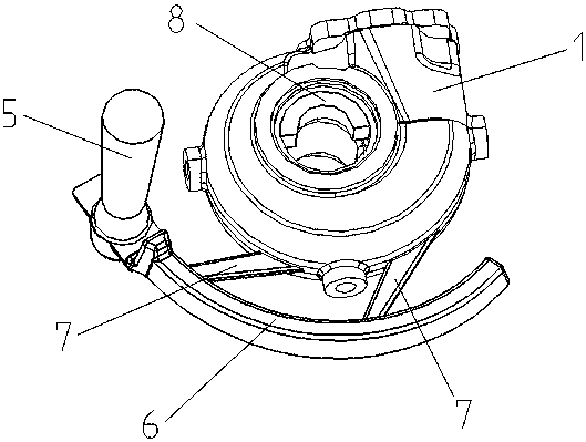
[0028] Such as Figure 2-3 As shown, the present invention provides a water-cooled turbine casing, including a casing 1, a sprue 5, a runner 6, an inner runner 7, and a special cooling iron 8;

[0029] The sprue 5 is arranged on one side of the housing 1 and is perpendicular to the ground, the runner 6 is arranged on one side of the housing 1 and is parallel to the ground, the sprue 5 is connected to the runner 6, The runner 6 is connected with an inrunner 7, two inrunners 7 are provided, and the inrunner 7 is connected to the shell 1; the shell 1 is provided with a water cavity.

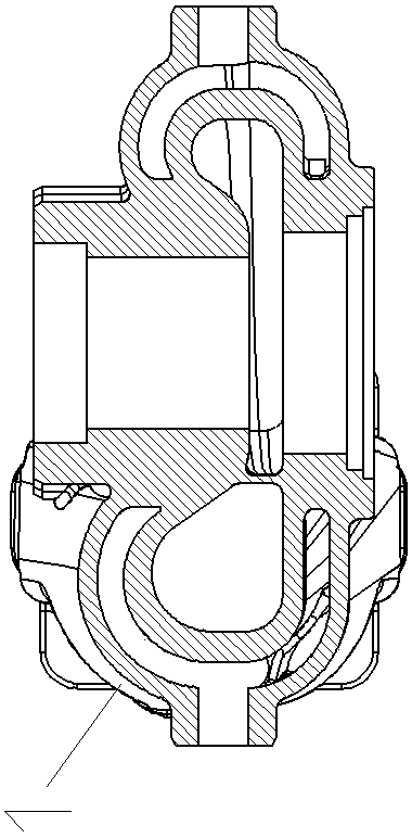
[0030] A cold iron 8 is placed in the inner hole of the housing 1 .

[0031] The housing 1 is a horizontal split structure.

[0032] The shape of the sprue 5 is cylindrical with a diameter of φ30-φ40mm.

[0033] The runner 6 is annular in shape and has a cross-sectional area of ​​1300-1600mm².

[0034] The shape of the ingate 7 is a sheet shape...

Embodiment 2

[0036] Casting process of embodiment 2 water-cooled turbine casing

[0037] The invention provides a casting process for a water-cooled turbine shell, comprising the following steps:

[0038] Step S1: placing the sprue 5 on one side of the casing 1;

[0039] Step S2: placing the runner 6 in a ring around the outside of the housing 1 and connecting it with the sprue 5;

[0040] Step S3, two inrunners 7 are opened on the runner 6, and the inrunners 7 are connected with the housing 1;

[0041] Step S4, placing a semicircular fan-shaped cold iron 8 in the inner hole of the housing 1;

[0042] Step S5, pouring molten iron from the sprue 5 during pouring, the molten iron flows through the runner 6 and then enters the cavity of the housing 1 through the two inrunners 7, and forms a turbine casing casting after cooling.

[0043] In the present invention, the molten iron is poured from the sprue 5, and the part of the inner hole that is prone to shrinkage is quenched by the cold iro...


PUM


Abstract

The invention discloses a water cooling turbine shell. The water cooling turbine shell comprises a shell body which is internally provided with a water cavity. The water cooling turbine shell also comprises a straight pouring channel, a transverse pouring channel and inner pouring channels. The straight pouring channel is arranged on one side of the shell body and is perpendicular to ground. The transverse pouring channel is arranged on one side of the shell body and is parallel to the ground. The straight pouring channel is connected with the transverse pouring channel and the transverse pouring channel is connected with the inner pouring channels. The number of the inner pouring channel is two. The inner pouring channels are connected with the shell body. A chill block is arranged in aninner hole of the shell body. The invention also provides a casting technology of the water cooling turbine shell. According to the water cooling turbine shell and the casting technology thereof, theproblem of low production rate of the water cooling turbine shell is solved; casting cost is lowered; the effect of sequential solidification from interior to exterior is achieved; casting defects arenot caused in a casting piece; a feeding head with heavy weight is omitted; the production rate is high; and production cost of the casting pieces is effectively lowered.

Description

technical field [0001] The invention discloses a water-cooled turbine casing and a casting process thereof, and relates to the technical field of turbochargers. Background technique [0002] The turbocharger is one of the most important parts of the engine at present. Under the condition of a certain engine displacement, it can effectively increase the output power of the engine, and has achieved the effect of saving energy and reducing consumption. The power source of the turbocharger is the high-temperature and high-pressure exhaust gas discharged from the engine. The exhaust gas enters the turbine housing of the turbocharger to drive the turbine to rotate. Therefore, the turbine housing needs a certain high temperature resistance and good heat dissipation performance. When the working environment is special Or when the heat dissipation capability is required to be high, the turbine casing is generally designed as a water-cooled turbine casing. Compared with the ordinary a...

Claims


Application Information

Patent Timeline
Patent Type & Authority Applications(China)
IPC IPC(8): B22C9/08B22C9/22
CPCB22C9/082B22C9/22
Inventor 刘法章陈慧勇孟庆国牟少华周建章陈晓明李玉振马永华傅江波
Owner 康诺精工有限公司
Why Eureka
Try Eureka