
Ladle bottom lining structure of hot metal ladle with spherical bottom and construction method thereof

A ladle and inner lining technology, which is applied in the direction of casting molten material containers, metal processing equipment, casting equipment, etc., can solve the problems of difficult construction control, difficult inner lining masonry, and loose combination, so as to prevent iron seepage and Hidden danger of iron seepage, convenient effect of masonry construction

Pending Publication Date: 2018-09-07
武汉精鼎科技股份有限公司
View PDF10 Cites 0 Cited by
  • Summary
  • Abstract
  • Description
  • Claims
  • Application Information

AI Technical Summary

Problems solved by technology

[0003] However, the bottom of the existing spherical bottom ladle must be built with wedge-shaped bricks, which have many brick shapes and difficult linings; in addition, the ladle is generally made of steel structures and refractory linings. At present, the refractory inner lining of the bottom bag is mostly made of shaped refractory products. It is generally composed of a permanent layer and a working layer. There are often gaps at the junction of the bottom working layer and the wall working layer, resulting in a loose combination and easy Iron seepage occurs; and during the masonry process, it is difficult to control the construction at the beginning of the center of the wrapping bottom and the junction of the wrapping bottom and the wrapping wall, which may easily cause quality problems

Method used


Image

  • Ladle bottom lining structure of hot metal ladle with spherical bottom and construction method thereof
  • Ladle bottom lining structure of hot metal ladle with spherical bottom and construction method thereof
  • Ladle bottom lining structure of hot metal ladle with spherical bottom and construction method thereof

Examples


Embodiment Construction

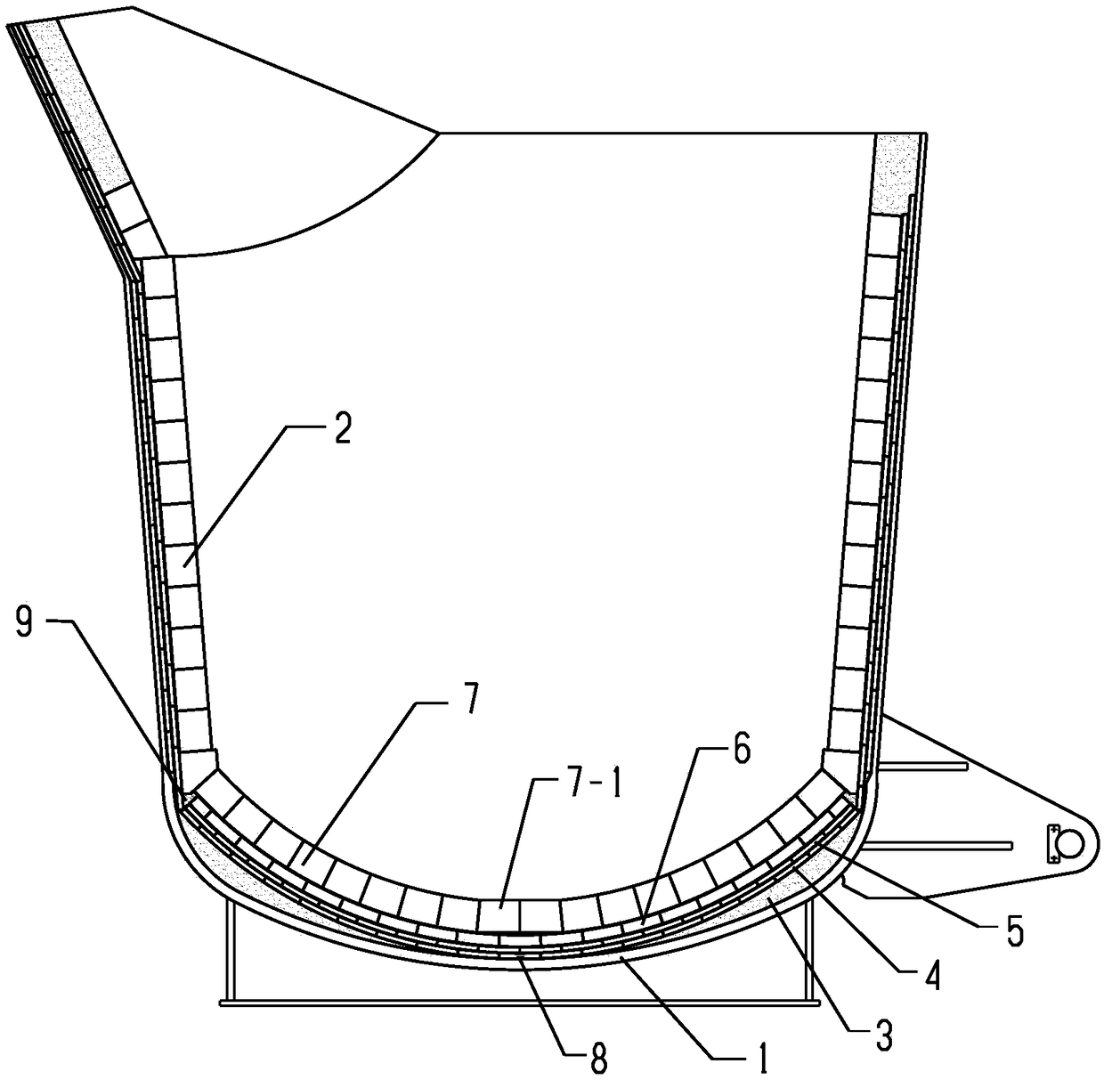
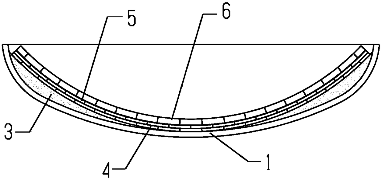
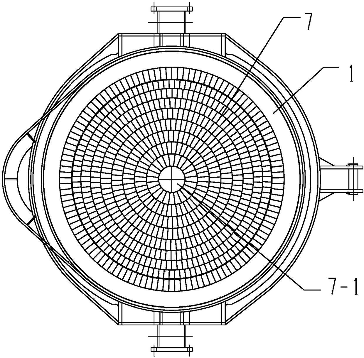
[0043] The present invention will be further described below in conjunction with drawings and embodiments. Such as figure 1 and figure 2 The ladle bottom lining structure of a kind of spherical bottom ladle shown, comprises permanent layer and ladle bottom working layer 7, as image 3 As shown, the bottom-covering working layer 7 is composed of a circular central part built by four central bricks 7-1 and a circular part formed by fan-shaped bricks by circular masonry. Each central brick 7-1 1 is a special-shaped brick with an arc-shaped cross section, and the four central bricks 7-1 have the same size and shape; the central brick and the fan-shaped brick of the bottom-covering working layer 7 are all made of aluminum silicon carbide refractory bricks. Such as figure 2 As shown, the permanent layer is sequentially composed of the first permanent layer 4, the second permanent layer 5 and the third permanent layer 6 from the outside to the inside, and a spherical tamping is ...


PUM

PropertyMeasurementUnit
radiusaaaaaaaaaa
diameteraaaaaaaaaa
diameteraaaaaaaaaa

Abstract

The invention provides a ladle bottom lining structure of a hot metal ladle with a spherical bottom and a construction method thereof. The lining structure comprises a permanent layer and a ladle bottom working layer. The permanent layer is composed of a first permanent layer, a second permanent layer and a third permanent layer from the outside to the inside in sequence. The specific constructioncomprises the steps that firstly a central round table is overlaid at the central position of a ladle bottom steel structure, a spherical ramming mass cushion is poured by using an arc-shaped plate as a datum; then three permanent layers are constructed in sequence, each permanent layer is placed at the central point with a special disc-shaped mould, the outer area is constructed around the mouldto the periphery; then the mould is removed, straight bricks are used for constructing a central area, and the construction direction of the center area of the every two adjacent permanent layers isopposite; and finally, the ladle bottom working layer is constructed, and the gap of the connection part between the ladle bottom and a ladle wall is poured and filled with corundum castables. According to the hot metal ladle after the construction, the service life of the hot metal ladle is prolonged, and the cost of refractory material of ton of steel is reduced on the premise of ensuring the safety of the hot metal ladle.

Description

technical field [0001] The invention relates to the field of iron and steel metallurgy, in particular to a refractory lining structure and a masonry method at the bottom of a ladle with a spherical bottom for containing molten iron. Background technique [0002] In the iron and steel metallurgy industry, ladles undertake the tasks of containing, desulfurizing and transferring molten iron. The existing molten iron ladle shell has two shapes: flat bottom and spherical bottom. The steel shell with the spherical bottom has good force resistance, high strength and good safety. During the pretreatment of molten iron, the shape of the flow field of molten iron in the ladle is ideal. , the mixing time is short, there is no "dead zone", which is conducive to the floating of inclusions after desulfurization, and the bottom refractory material of the ball bottom ladle has good corrosion resistance and impact resistance, which is conducive to the safe use of the ladle. Since the molten...

Claims


Application Information

Patent Timeline
Patent Type & Authority Applications(China)
IPC IPC(8): B22D41/02
CPCB22D41/02B22D41/023
Inventor 王成春张炳祥
Owner 武汉精鼎科技股份有限公司
Learn More