Steam setting device for printing and dyeing cloth

A steam setting and cloth feeding device technology, applied in the field of textile machinery and setting machines, can solve the problems of increasing production costs, polluting the environment, and unequal wrinkles, and achieve the effects of improving the setting effect, reducing pollution, and facilitating processing

Pending Publication Date: 2018-09-07
海盐鸳鸯丝绸印染股份有限公司
View PDF7 Cites 10 Cited by
  • Summary
  • Abstract
  • Description
  • Claims
  • Application Information

AI Technical Summary

Problems solved by technology

[0002] China is a big textile country, and the textile industry is one of the economic centers of our country. In the production process of printing and dyeing enterprises in the textile industry, after the cloth is printed, dyed and washed, its surface will be wrinkled and uneven, and it must be dried and shaped. The existing drying and shaping Most of the devices use heat transfer oil as the heat source. The advantage is that the temperature is high and the heat source is fully utilized, but there are also many disadvantages: firstly, because the heat source is heat transfer oil, there are safety problems; secondly, most of these stereotyped heating devices are Small heat-conducting oil boilers generally have a processing capacity of less than 5 tons per hour, and most of them are coal-fired boilers that have not been desulfurized, denitrified and effectively dedusted, which seriously pollute the environment. With the emphasis on environmental protection in our country, in order to strengthen supervision, many Cities have also adopted the method of abolishing small boilers and adopting steam central heating instead. Most enterprises have also carried out technical transformation. Some steam setting machines have also appeared on the market. However, due to the low temperature of the heat source, the heat loss and utilization rate are low. High, thus increasing the production cost of the enterprise

Method used


Image

  • Steam setting device for printing and dyeing cloth

Examples


Embodiment Construction

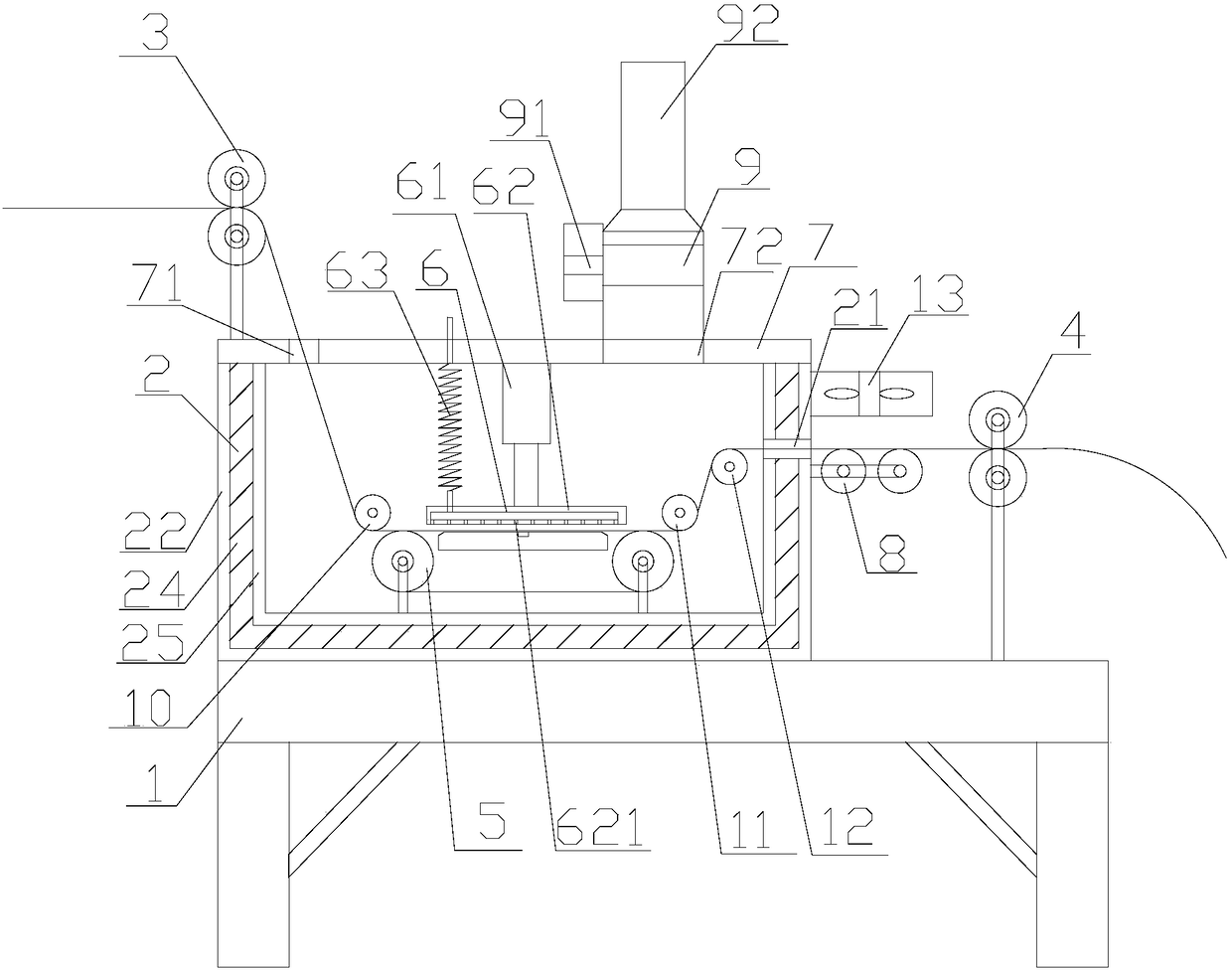
[0015] refer to figure 1 , a printing and dyeing cloth steam setting device of the present invention, comprising a frame 1, a shaping box 2, a cloth feeding device 3, a cloth discharging device 4, a conveyor belt 5, a steam pressing device 6, a case cover 7, a water cooling roller 8, an exhaust Device 9, the first cloth guide roller 10, the second cloth guide roller 11, the third cloth guide roller 12, the frame 1 is provided with a shaping box 2, and the upper end of the shaping box 2 is provided with There is a box cover 7, and the box cover 7 is detachably connected with the stereotyped box body 2. The upper end of the box cover 7 is provided with a cloth feeding device 3, and the box cover 7 is provided with a cloth feeding device 3. Cloth inlet 71, described box cover 7 is provided with air outlet 72, and described air outlet 72 upper end is provided with air exhaust device 9, and described stereotyped casing 2 inner chamber lower end is provided with conveyer belt 5, so ...


PUM


Abstract

The invention discloses a steam setting device for printing and dyeing cloth, comprising a rack, a setting box, a cloth inlet device, a cloth outlet device, a conveyor belt, a steam pressing device, abox cover, a water cooling roller, an air exhaust device, a first cloth guide roller, a second cloth guide roller and a third cloth guide roller, wherein the setting box is arranged on the rack, thebox cover is arranged at the upper end of the setting box, the box cover is detachably connected with the setting box, and the cloth inlet device is arranged at the upper end of the box cover. According to the invention, the steam pressing device is arranged to perform hot stamping on the cloth, so as to save energy and reduce pollution to environment; cloth is conveyed due to the arrangement of the cloth inlet device, the cloth outlet device and a plurality of cloth guide rollers, so that the cloth is kept smooth in the conveying process; the air exhaust device is arranged to concentrate waste gas, so as to be convenient for processing; due to the match of the water cooling roller and a cooling fan, sized cloth is cooled and air-dried at the first time, so as to improve the sizing effectand facilitate subsequent operation.

Description

【Technical field】 [0001] The invention relates to the technical field of textile machinery, especially the technical field of setting machines. 【Background technique】 [0002] China is a big textile country, and the textile industry is one of the economic centers of our country. In the production process of printing and dyeing enterprises in the textile industry, after the cloth is printed, dyed and washed, its surface will be wrinkled and uneven, and it must be dried and shaped. The existing drying and shaping Most of the devices use heat transfer oil as the heat source. The advantage is that the temperature is high and the heat source is fully utilized, but there are also many disadvantages: firstly, because the heat source is heat transfer oil, there are safety problems; secondly, most of these stereotyped heating devices are Small heat-conducting oil boilers generally have a processing capacity of less than 5 tons per hour, and most of them are coal-fired boilers that ha...

Claims


Application Information

Patent Timeline
Patent Type & Authority Applications(China)
IPC IPC(8): D06B19/00D06B23/04D06B23/20D06B15/09
CPCD06B15/09D06B19/00D06B23/04D06B23/20
Inventor 许加生
Owner 海盐鸳鸯丝绸印染股份有限公司
Why Eureka
Try Eureka