Gas turbine engine

A gas turbine and engine technology, applied in the direction of gas turbine devices, engine components, machines/engines, etc., can solve the problems of energy waste and insufficient energy utilization, and achieve the effects of sufficient kinetic energy, long action time, and high control accuracy

Inactive Publication Date: 2018-09-07
HITACHI AUTOMOTIVE SYST SUZHOU
View PDF8 Cites 0 Cited by
  • Summary
  • Abstract
  • Description
  • Claims
  • Application Information

AI Technical Summary

Problems solved by technology

But as mentioned earlier, such an improvement does not make full use of the energy in the discharged exhaust gas, which will cause a great waste of energy

Method used


Image

  • Gas turbine engine
  • Gas turbine engine
  • Gas turbine engine

Examples


no. 1 example

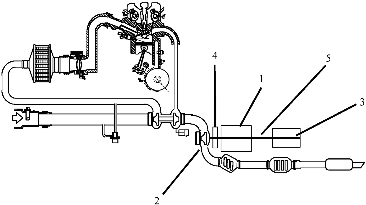
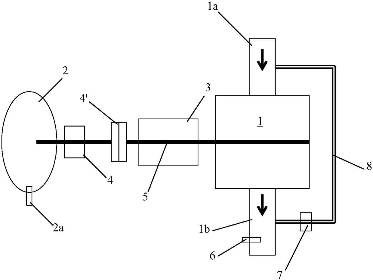
[0054] figure 1 is a structural schematic diagram of a gas turbine engine according to the present invention, and figure 2 Then it shows the first embodiment according to the present invention, in which the connection relationship between the oil pump 1 , the oil pump turbine 2 and the electric machine 3 of the gas turbine engine is briefly shown.

[0055] In the first embodiment of the present invention, the motor 3 is mainly used to drive the oil pump 1 , and the power of the turbine 2 of the oil pump is used as the supplementary power of the motor 3 .

[0056] Specifically, in the gas turbine engine of the first embodiment, the oil pump 1 is associated with the electric machine 3 through the shaft 5, and the electric machine 3 is coaxially connected to the oil pump turbine 2 by means of the reduction gear set 4 and the electromagnetic clutch 4' . A turbine rotational speed sensor 2 a may also be provided to detect the rotational speed of the oil pump turbine 2 . At this...

no. 2 example

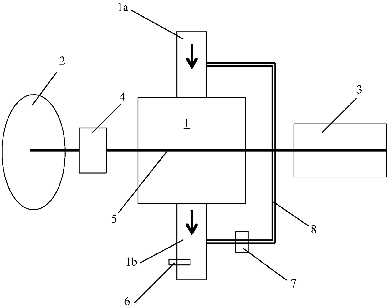
[0063] image 3 A second embodiment according to the present invention is shown, in which the connection relationship between the oil pump 1 , the oil pump turbine 2 and the electric machine 3 of the gas turbine engine is briefly shown.

[0064] In the second embodiment of the present invention, the power of the oil pump turbine 2 is mainly used to drive the oil pump 1, and the power of the motor 3 is used as supplementary power, and the remaining kinetic energy is used to drive the motor 3 to generate electricity.

[0065] Specifically, in the gas turbine engine of the second embodiment, the oil pump 1 is associated on the one hand with the electric machine 3 via the shaft 5 and is coaxially connected to the oil pump turbine 2 with the reduction gear set 4 on the other hand. At this time, different from the first embodiment, the motor 3 and the oil pump turbine 2 are located on both sides of the oil pump 1 , and work on the oil pump 1 through the shaft 5 .

[0066] The oil p...


PUM


Abstract

The invention relates to a gas turbine engine. An oil pump (1) of the gas turbine engine is equipped with an oil pump turbine (2), and exhaust gas discharged from the gas turbine engine drives the oilpump (1) via the oil pump turbine (2). The oil pump turbine of the invention is connected with the oil pump in the whole course, so action time is longer; a precise logic can also be set, oil pressure is controlled by an ECU, and a bypass is arranged for pressure relief, so control precision is higher. In addition, a motor is driven while the oil pump turbine is driven; and at the time, the motorhas a power generation function and can charge a storage battery, so kinetic energy in the exhaust gas of the engine can be more fully utilized.

Description

technical field [0001] The invention relates to a gas turbine engine. More specifically, it relates to a gas turbine engine that utilizes energy in exhaust gases to drive an oil pump. Background technique [0002] As we all know, the exhaust gas discharged from the engine has great mechanical energy and thermal energy, most of which have not been fully utilized. In order to utilize the above-mentioned mechanical energy and thermal energy, turbocharged engines have been widely used. However, a large portion of the kinetic energy in the exhaust gases from a turbocharged engine remains unused. [0003] Specifically, the turbocharged engine has its turbine in a non-working state under some operating conditions. When the turbine is not working, the exhaust valve is in the open position. At this time, the exhaust gas from the engine does not work on the turbine, but directly enters the exhaust pipe. Therefore, most of the energy of the exhaust gas is not utilized. Under high...

Claims


Application Information

Patent Timeline
IPC IPC(8): F02C6/00F02C7/06F01D15/08F01D15/10
CPCF02C6/00F01D15/08F01D15/10F02C7/06
Inventor 张斌伟
Owner HITACHI AUTOMOTIVE SYST SUZHOU
Why Eureka
Try Eureka