Bio-particle fuel burner

A technology of biological particles and burners, which is applied to the combustion, combustion and ignition of solid fuels, combustion methods, etc., can solve the problems of difficulty in improving the automation level of feeding, expanding the source of granular materials, and inability to directly input sawdust, etc., so as to improve the utilization rate of energy. , The effect of improving fuel utilization and rapid ignition

Inactive Publication Date: 2013-12-11
蔡春祥
View PDF9 Cites 12 Cited by
  • Summary
  • Abstract
  • Description
  • Claims
  • Application Information

AI Technical Summary

Problems solved by technology

Such an adjustment method will cause a large amount of fuel loss, but it will consume more energy and even require other fuel engines to assist, losing the environmental protection effect brought by using plant waste as the combustion medium, and its feeding system uses equipment Directly transporting granular fuel to the combustion chamber, this feeding method is not conducive to expanding the source of granular materials, for example, it cannot directly input sawdust, and it is difficult to improve the automation level of feeding, and the feeding equipment is more limited. In addition, the combustion flame in the combustion chamber has backflow The risk of returning the feeding channel and burning the machine

Method used


Image

  • Bio-particle fuel burner
  • Bio-particle fuel burner
  • Bio-particle fuel burner

Examples


Embodiment Construction

[0016] The present invention will be further described in conjunction with the accompanying drawings and specific embodiments.

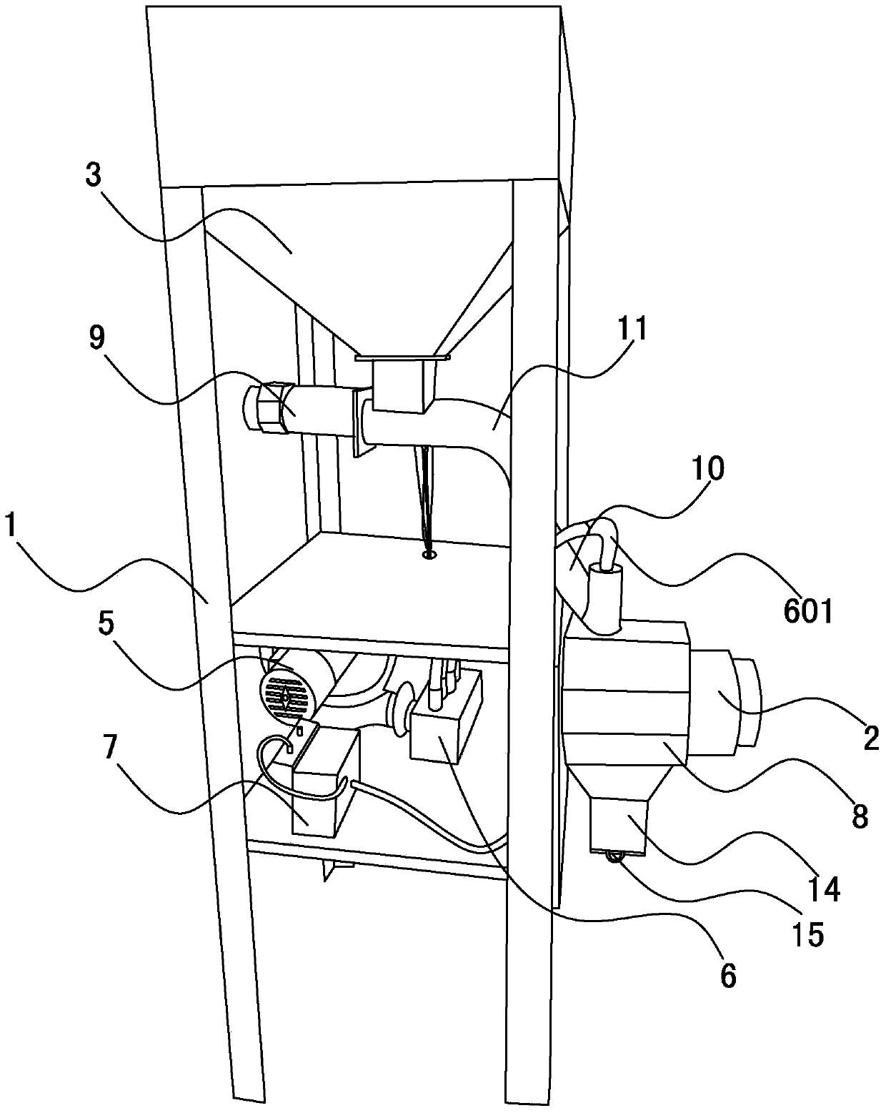
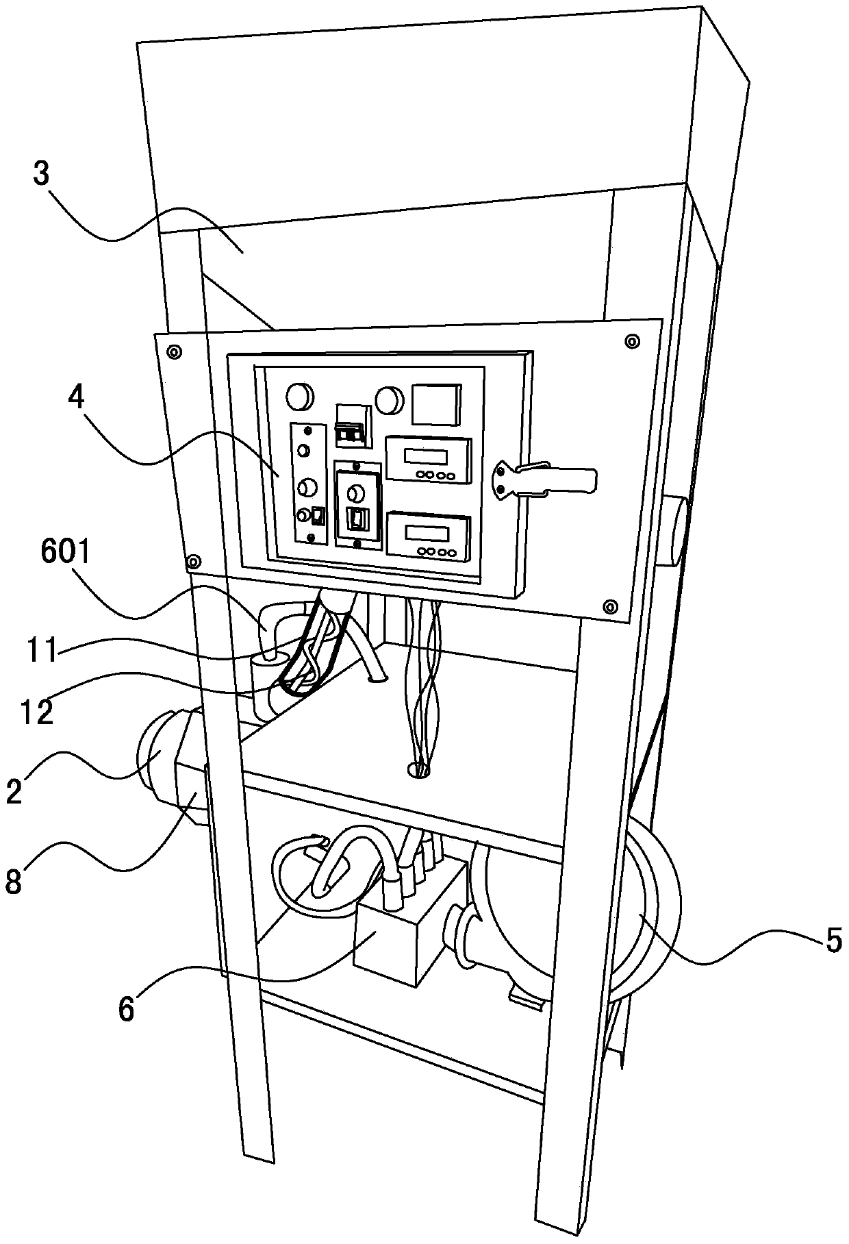
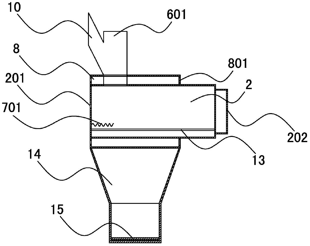
[0017] refer to figure 1 , figure 2 , image 3 , the biomass pellet fuel burner of the present invention comprises a frame 1 and a combustion chamber 2, a feed bin 3, a PLC controller 4, a temperature sensor, a blower 5, an air adjustable splitter device 6, and an ignition device arranged on the frame 1 7. Waste heat recovery device 8, alarm and material detector, the silo 3 is provided with a discharge device 9, the combustion chamber 2 is provided with a feed pipe 10 communicated with the discharge device of the silo 3, the The temperature sensor is located in the combustion chamber 2, and the air blower 5 is connected with the air inlet 201 of the combustion chamber 2 through the air adjustable splitter 6 to adjust the firepower of the combustion chamber 2 fire outlet 202, and the air adjustable splitter 6 The gas outlet 601 of the shunt outpu...


PUM


Abstract

The invention relates to fuel-burning equipment and provides a bio-particle fuel burner. According to the bio-particle fuel burner, the burner fast to ignite can reduce fuel loss, improve the utilization efficiency of fuel, save energy and protect environment, a machine table operates safely and stably, the burning power is large and the automatic level is high. The bio-particle fuel burner comprises a machine frame, a combustion chamber, a bin, a PLC, a temperature sensor and an air blower, wherein the combustion chamber, the bin, the PLC, the temperature sensor and the air blower are arranged on the machine frame. The bio-particle fuel burner further comprises an adjustable-air flow-distributing device and an ignition device. The bin is provided with a discharge device. The combustion chamber is provided with a feed pipe communicated with the discharge device of the bin. The air blower is communicated with an air inlet of the combustion chamber through the adjustable-air flow-distributing device. A flow-distributing output pipe air outlet of the adjustable-air flow-distributing device is further communicated with a feed pipe discharge opening of the combustion chamber. The ignition device comprises an ignition transformer and an electric stove wire connected with the ignition transformer. The electric stove wire is arranged in the combustion chamber. The PLC is connected with the discharge device, the ignition transformer, the temperature sensor and the adjustable-air flow-distributing device respectively.

Description

technical field [0001] The invention relates to combustion equipment, in particular to a biomass particle fuel burner. Background technique [0002] At present, the supply of conventional energy, such as coal, oil, and natural gas, is becoming increasingly tight, and the application cost has been rising. In addition, people's awareness of environmental protection continues to increase, and new energy development technologies have also made significant progress. In this context, various new energy sources have entered large-scale applications, such as wind energy, solar energy, and biomass energy. For biomass energy, large-scale agricultural and forestry production provides a steady stream of raw materials, such as corn stalks, rice husks, peanut shells, corncobs, sawdust, wood shavings, etc. As the main equipment for biomass energy utilization, the biomass pellet fuel burner has received extensive attention in the industry. In the prior art, the ignition speed of the bio...

Claims


Application Information

Patent Timeline
Patent Type & Authority Applications(China)
IPC IPC(8): F23B50/00F23Q7/02F23N1/02F23K3/16
Inventor 蔡春祥
Owner 蔡春祥
Why Eureka
Try Eureka