Electric thermal storage preheating steam generator

A technology of steam generator and electric heat storage, which is applied in the direction of steam generation, steam generation method, preheating water accumulator, etc., which can solve the problems of large electric load impact, large electric load impact, and high operating cost, and achieve reduction Power load, high foresight, and the effect of improving the overall thermal efficiency

Pending Publication Date: 2018-09-07
中建环能建筑工程有限公司
View PDF0 Cites 3 Cited by
  • Summary
  • Abstract
  • Description
  • Claims
  • Application Information

AI Technical Summary

Problems solved by technology

However, these electric steam generators use electricity as a heating source, and the steam usage peak of steam users often occurs during the peak electricity and peak time periods when the electricity price is higher during the day, resulting in higher operating costs of the system, and during the peak stea

Method used


Image

  • Electric thermal storage preheating steam generator
  • Electric thermal storage preheating steam generator

Examples


Embodiment 1

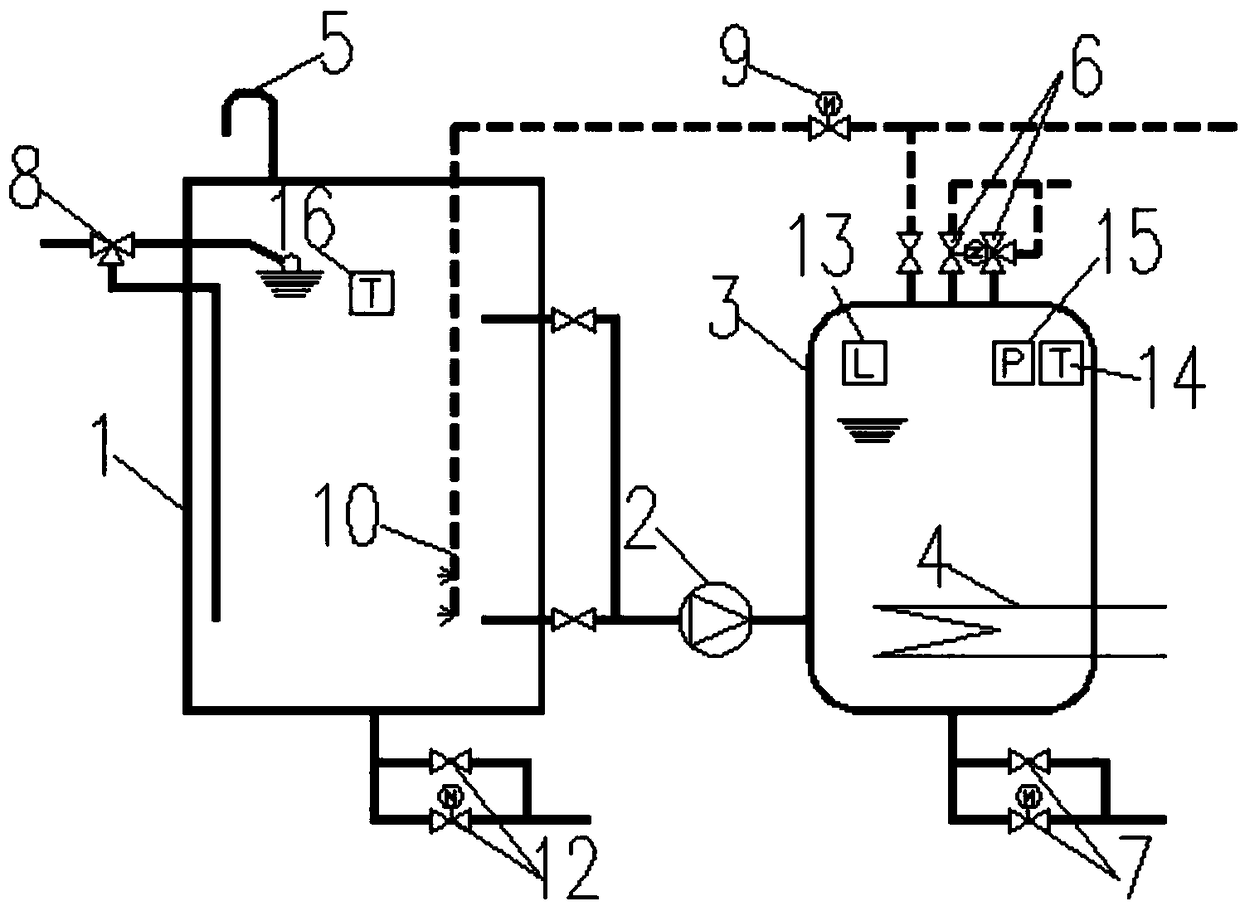
[0026] like figure 1 As shown, an electric heat storage preheating steam generator includes a heat storage open water tank 1, and the heat storage open water tank 1 is a device for heat storage and preheating of the steam water replenishment system during the night low valley electricity and daytime parity electricity period. The heat-opening water tank 1 is provided with an upper water outlet and a lower water outlet, both of which are connected to the suction port of the booster pump 2. Since the water temperature at the top of the heat-storage open water tank 1 is relatively high, the booster pump usually 2. The upper water outlet is pumped, and the lower water outlet is used as an emergency water outlet. The outlet of the pressurizing pump 2 is connected to the water inlet of the heating pressurized water tank 3 for replenishing the heated pressurized water tank 3 . The top of the heat storage open water tank 1 is provided with a breathing tube 5, which is used as a means ...

Embodiment 2

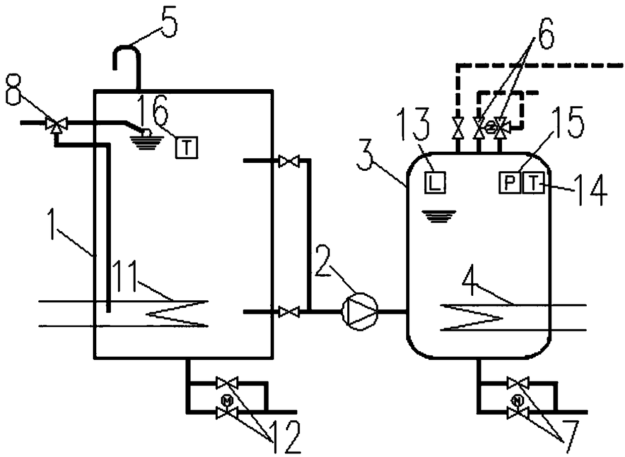
[0030] like figure 2 As shown, an electric heat storage preheating steam generator includes a heat storage open water tank 1, and the heat storage open water tank 1 is a device for heat storage and preheating of the steam water replenishment system during the night low valley electricity and daytime parity electricity period. The heat-opening water tank 1 is provided with an upper water outlet and a lower water outlet, both of which are connected to the suction port of the booster pump 2. Since the water temperature at the top of the heat-storage open water tank 1 is relatively high, the booster pump usually 2. The upper water outlet is pumped, and the lower water outlet is used as an emergency water outlet. The outlet of the pressurizing pump 2 is connected to the water inlet of the heating pressurized water tank 3 for replenishing the heated pressurized water tank 3 . The top of the heat storage open water tank 1 is provided with a breathing tube 5, which is used as a means...


PUM


Abstract

The invention discloses an electric thermal storage preheating steam generator. The electric thermal storage preheating steam generator comprises a thermal storage open type water tank. A water outletof the thermal storage open type water tank is connected with a suction inlet of a pressure pump. An outlet of the pressure pump is connected with a water inlet of a heating pressure-bearing water pot. A heating device and a second temperature sensor are arranged inside the thermal storage open type water tank. A first electric heater, a liquid level sensor, a pressure sensor and a first temperature sensor are arranged inside the heating pressure-bearing water pot. A safety valve and a steam outlet are arranged on the top of the heating pressure-bearing water pot. The electric thermal storagepreheating steam generator can preheat water with low-price electricity at the periods of valley electricity at night and common-price electricity during daytime, steam is generated through preheatedhot water when steam is needed for use, the electrical load during steam generation is decreased, the operating cost of a system is reduced then, and the electrical load of the system is decreased aswell.

Description

technical field [0001] The invention relates to the technical field of steam supply, in particular to a steam generator. Background technique [0002] There are many fields that need to use steam in daily production and life, such as hotels, schools, laboratories, food processing, industrial manufacturing and other fields. [0003] Usually, the sources of steam include municipal centralized steam supply system, regional steam supply system, and distributed steam supply system. [0004] Production steam heating heat sources include power plant extraction to supply steam, coal-fired boilers to produce steam, gas-fired boilers to produce steam, oil-fired boilers to produce steam, electric boilers to produce steam, etc. [0005] Different steam users have different steam usage characteristics. Industrial users usually use relatively small changes in steam consumption, relatively stable steam consumption, low heat loss, and high efficiency of pipes and boilers; while buildings u...

Claims


Application Information

Patent Timeline
IPC IPC(8): F22B1/28F22D3/00
CPCF22B1/28F22D3/00
Inventor 李立华陈丽君杨春辉
Owner 中建环能建筑工程有限公司
Why Eureka
Try Eureka