Ultra-high temperature mechanical and thermal coupling strain gauge and working method based on reflection x-ray in-situ experiment

An X-ray and reflective technology, applied in the field of high-temperature mechanical-thermal coupling strain gauges, can solve the problems of lack of test benches, difficulty in tracking observation positions, and deficiencies, and achieve the effect of reducing mechanical drift

Active Publication Date: 2019-02-26
XI AN JIAOTONG UNIV
View PDF5 Cites 0 Cited by
  • Summary
  • Abstract
  • Description
  • Claims
  • Application Information

AI Technical Summary

Problems solved by technology

However, there are still deficiencies in the in-situ experimental bench for reflection X-ray diffraction
Due to the lack of a test bench capable of achieving ultra-high temperature (>1100°C) force-thermal coupling, and the drift of the sample due to the thermal expansion of the test bench components at high temperatures, it is difficult to track the same observation position and obtain high-precision measurements

Method used


Image

  • Ultra-high temperature mechanical and thermal coupling strain gauge and working method based on reflection x-ray in-situ experiment
  • Ultra-high temperature mechanical and thermal coupling strain gauge and working method based on reflection x-ray in-situ experiment
  • Ultra-high temperature mechanical and thermal coupling strain gauge and working method based on reflection x-ray in-situ experiment

Examples


Embodiment Construction

[0025] The present invention will be described in further detail below in conjunction with the drawings and specific embodiments.

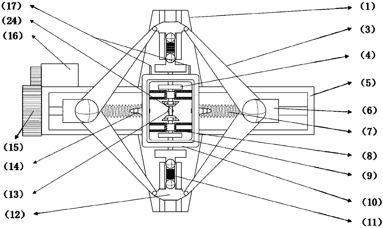
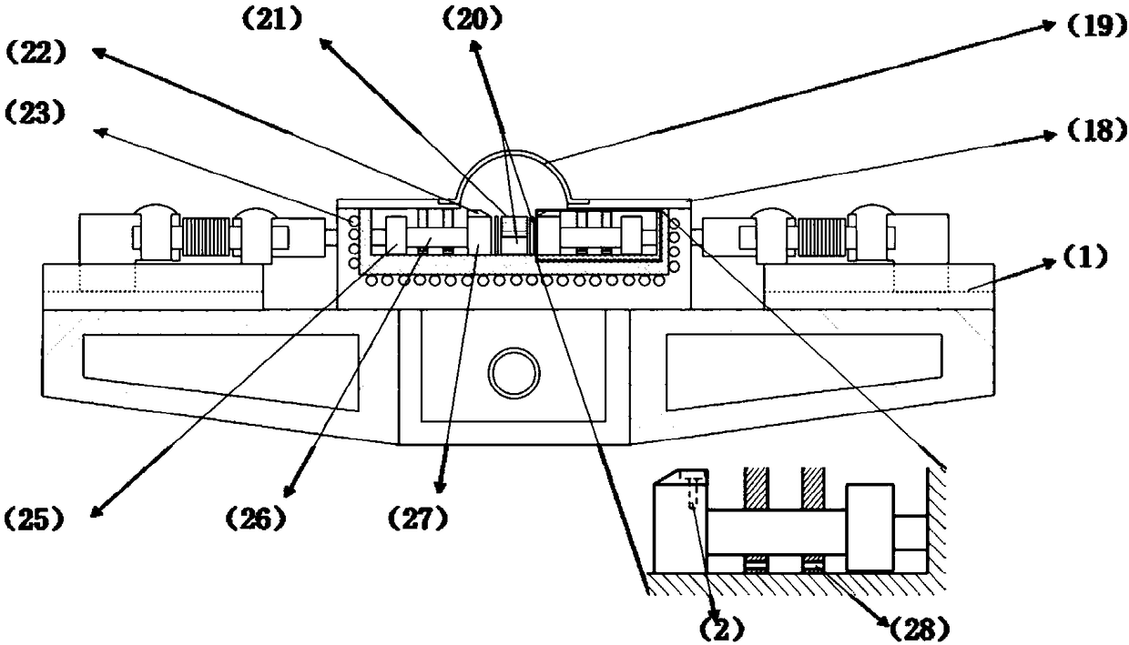
[0026] like figure 1 and figure 2As shown, the present invention is based on a reflective X-ray in-situ experiment ultra-high temperature mechanical-thermal coupling strain gauge, including a base 5, a bidirectional screw 7 installed in the base 5 parallel to the long side of the base, the bidirectional screw 7 is driven by a motor 16 and a transmission group 15 transmission to realize movement, with the help of the two-way screw 7 to realize the moving block 6 that moves in the opposite direction, the moving block 6 is set on both sides of the two-way screw 7 and placed oppositely; four connecting rods 3 are connected in pairs to form a quadrilateral structure, and two diagonal nodes are connected to move Block 6, a pair of sliders 12 are installed on the other two diagonal nodes of the unconnected moving block 6 and placed on the slide rail 1 ...


PUM

PropertyMeasurementUnit
diameteraaaaaaaaaa
thicknessaaaaaaaaaa
widthaaaaaaaaaa

Abstract

The invention provides an ultrahigh-temperature thermo-mechanical coupling strain gauge based on a reflection type X-ray in-situ experiment and a working method. The strain gauge comprises a base, a bidirectional screw rod which is mounted in the base and is parallel to a long edge and movable blocks which do relative motion through the bidirectional screw rod, wherein the movable blocks are connected with four connecting rods; the four connecting rods are connected two by two to form a quadrilateral structure; a pair of sliding blocks are relatively arranged at the other two nodes which are not connected with the movable blocks, and are arranged on sliding rails respectively; the sliding blocks are connected with a pair of sample clamps through piezoelectric sensors in a direction vertical to the bidirectional screw rod; the sample clamps penetrate through a shell inner wall and a shell outer wall and then penetrate through heat insulation walls to get close to a heating module; gas path connectors are mounted at the centers of long edges of the shell inner wall and the shell outer wall respectively; a cooling pipe is mounted between the shell inner wall and the shell outer wall;upper covers are mounted above the shell inner wall and the shell outer wall. According to the ultrahigh-temperature thermo-mechanical coupling strain gauge, the conversion of atmosphere environmentscan be realized and mechanical drift caused by thermal expansion is reduced; ultrahigh-temperature experiment conditions are realized and adverse effects caused by ultrahigh temperature on a moving mechanism are avoided.

Description

technical field [0001] The invention relates to an ultra-high temperature force-thermal coupling strain gauge based on reflection X-ray in-situ experiments, and in particular to an ultra-high temperature, high-precision, multi-atmosphere force-thermal coupling strain gauge applied to reflection X-ray in-situ experiments and working methods. Background technique [0002] In order to be suitable for the extreme use environment of aero-engines, single crystal nickel-based superalloys are used in the manufacture of engine blades due to their high-temperature oxidation resistance and excellent creep resistance (T.M.Pollock, et al.Nickel-based Superalloys for advanced turbine engines : chemistry, microstructure and properties, J. Propul. Power 2006). However, the manufacturing, processing and maintenance costs of engine blades are high. For the repair of engine blades, 3D printing technology is regarded as an ideal solution. If 3D printing technology is used to directly repair cr...

Claims


Application Information

Patent Timeline
Patent Type & Authority Patents(China)
IPC IPC(8): G01N3/18G01N3/02G01N3/06G01N23/223
CPCG01N3/02G01N3/06G01N3/066G01N3/18G01N23/223G01N2203/0017G01N2203/005G01N2203/0226G01N2203/0623G01N2203/0641
Inventor 陈凯沈昊
Owner XI AN JIAOTONG UNIV
Why Eureka
Try Eureka