
Orthogonal electrostatic suspension accelerometer sensitive structure

An accelerometer and electrostatic levitation technology, applied in speed/acceleration/shock measurement, acceleration measurement using inertial force, fluid velocity measurement, etc., can solve complex support circuit system, high ground support suspension voltage, large support circuit error, etc. problem, to achieve the effect of simplifying the measurement and control circuit, compact overall structure and expanding the measuring range

Active Publication Date: 2018-09-07
TSINGHUA UNIV
View PDF8 Cites 2 Cited by
  • Summary
  • Abstract
  • Description
  • Claims
  • Application Information

AI Technical Summary

Problems solved by technology

[0007] For micro-electrostatic accelerometers using MEMS technology, due to design and process limitations, most of them adopt an asymmetric structure between one axis and the other two axes, and it is difficult to achieve three-axis measurement consistency
For the accelerometer for three-axis measurement, the three-axis electrostatic accelerometer with liquid medium in the prior art has the same three-axis parameters, but the principle and structure are relatively complicated, and the processing and assembly procedures are relatively complicated.
[0008] At present, the main problem of the electrostatic levitation accelerometer is that the ground support levitation voltage is high, which brings problems such as complex support circuit system and large support circuit error, and it is difficult to achieve high precision and high stability.
In addition, most of the existing accelerometer designs are asymmetrical in structure and measurement parameters in all directions, making it difficult to achieve three-axis measurement, or the measurement consistency of each axis is not good

Method used


Image

  • Orthogonal electrostatic suspension accelerometer sensitive structure
  • Orthogonal electrostatic suspension accelerometer sensitive structure
  • Orthogonal electrostatic suspension accelerometer sensitive structure

Examples


Embodiment Construction

[0036] Embodiments of the present invention are described in detail below, examples of which are shown in the drawings, wherein the same or similar reference numerals designate the same or similar elements or elements having the same or similar functions throughout. The embodiments described below by referring to the figures are exemplary only for explaining the present invention and should not be construed as limiting the present invention.

[0037] In describing the present invention, it should be understood that the terms "center", "longitudinal", "transverse", "length", "width", "thickness", "upper", "lower", "front", " Back", "Left", "Right", "Vertical", "Horizontal", "Top", "Bottom", "Inner", "Outer", "Clockwise", "Counterclockwise", "Axial", The orientation or positional relationship indicated by "radial", "circumferential", etc. is based on the orientation or positional relationship shown in the drawings, and is only for the convenience of describing the present invent...


PUM


Abstract

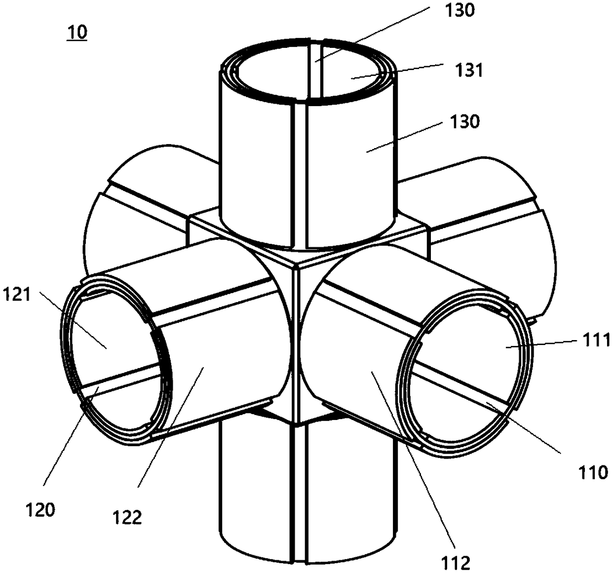
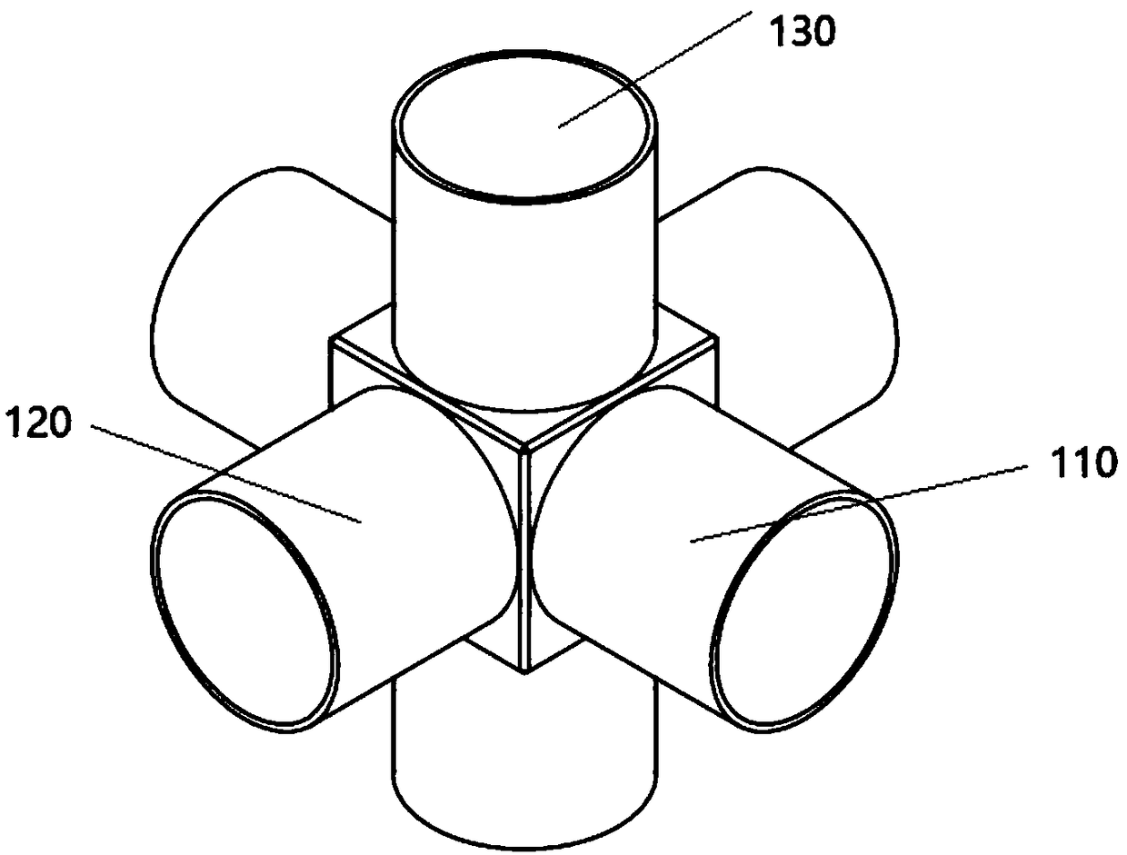
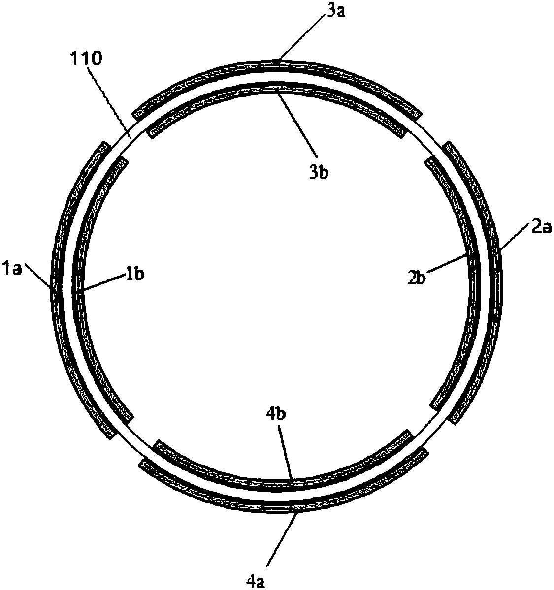
The present invention discloses an orthogonal electrostatic suspension accelerometer sensitive structure. The structure comprises a sensitive mass block and electrodes, the sensitive mass block comprises an X-axis measurement tube, a Y-axis measurement tube and a Z-axis measurement tube which are respectively extended along an X axis, a Y axis and a Z axis, there are the plurality of electrodes which are in non-contact installation on the sensitive mass block to apply electrostatic suspension force and feedback control force to the sensitive mass block to allow the sensitive mass block to be asuspension state. According to the orthogonal electrostatic suspension accelerometer sensitive structure, and the sensitive mass block forms a hollow structure to allow the electrodes in the same support voltage to provided large support forces to enlarge the measuring range. Besides, the structure is compact in the whole structure to achieve synchronous measurement of three-axes accelerated speeds, high measurement integration, good implementation of synchronism of each-axis measurement and control and simplify the measurement and control circuit.

Description

technical field [0001] The invention relates to the sensitive structure of the accelerometer, in particular to the sensitive structure design and electrode configuration scheme of the electrostatic levitation accelerometer. Background technique [0002] Aeronautical gravimeters and other gravity measurement equipment require the measurement accuracy of gravity anomalies to reach 1mGal (1×10 -6 g), correspondingly requiring accuracy better than 1×10 -6 g's accelerometer acts as a gravity sensor. [0003] The electrostatic levitation accelerometer is a force balance accelerometer that relies on electrostatic force to achieve non-contact levitation of the inspection mass. It is characterized by easy realization of small range, high precision and high stability. It can simultaneously measure the linear acceleration of the carrier in three orthogonal directions. A single instrument can realize the function of the three-axis accelerometer component required by the inertial navig...

Claims


Application Information

Patent Timeline
IPC IPC(8): G01P15/08
CPCG01P15/08G01P5/18
Inventor 张嵘贺晓霞韩丰田
Owner TSINGHUA UNIV
Learn More